Arduino (RF-)Nano with two SPI Devices

Hello,

I've been trying to find an answer for quite a bit, but I can't seem to find one that helps me with my Problem or I can understand as I'm quite new to this..

Anyways. My Goal is to read data from an XBox 360 Controller and send this data to a second Arduino.
For that I am using the "Mini USB Host Shield 2.0" (https://www.aliexpress.com/item/4001090390430.html?spm=a2g0s.9042311.0.0.487b4c4dw831rB) and the "Keywish RF-Nano" (Page Not Found - Aliexpress.com), which is basically a normal Arduino Nano with an NRF24L01+ Module attached to it.
I can either read the Controllers Data or send some generated messages with said Arduino, but I'm NOT able to do both. As far as I understood, this doesn't work, because both functions relay on the SPI functions of the boards.

So how can I use multiple SPI-Devices with one Arduino Nano?

In my research I found, that one can use multiple SS pins to activate and deactivate the devices and by cycling this I can listen to one devise and write to the next devise in the next instance... But how would I do this in code?
(To make it more clear, we can say that I use an Arduino Nano with the NRF24L01+ Module and the USB Shield connected to it)

One other concern is, that the pin out sheet for the Nano just states one SS Pin... Would Daisy-chaining the SPI bus work? How would i go about this?

I would be really greatfull for some help!

Hi

this link have a good info:
http://www.learningaboutelectronics.com/Articles/Multiple-SPI-devices-to-an-arduino-microcontroller.

mroobbo:
In my research I found, that one can use multiple SS pins to activate and deactivate the devices and by cycling this I can listen to one devise and write to the next devise in the next instance... But how would I do this in code?

What pin on the nano does the USB shield use for SS?

You just need to make sure that the nRF24 is not using that pin and then set the aprorpriate SS pin HIGH LOW for the device you want to communicate with. (The nRF24 documentation may refer to the pin as CSN)

...R

EDIT ... Apologies for mixing up HIGH and LOW

So it feels like I almost got it to work. But not quite. I did some changes to my Setup. I learned that it should be possible for multiple devices to connect to the Arduino over SPI. All devices can share the SCK, MOSI and MISO pins. But they each need to have there own SS pin. That's what I did.


Here is the test code I'm using:

#include <SPI.h>
#include <nRF24L01.h>
#include <RF24.h>

#include <XBOXUSB.h>

// Satisfy the IDE, which needs to see the include statment in the ino too.
#ifdef dobogusinclude
  #include <spi4teensy3.h>
#endif


#define CE_PIN_RADIO  7 //CE : set high to receive wireless data, low to send
#define CSN_PIN_RADIO 8 //Same as SS: SPI enable pin, set low to listen to SPI bus.
//SS Pin USB needs to stay standard (PIN D10) I don't know how to change it
#define SS_PIN_USB 10

int i = 0;

const uint64_t pipe = 0x1; // This is the transmit pipeline
int sendData[1];  // One element array holding our random number

RF24 radio(CE_PIN_RADIO, CSN_PIN_RADIO); // Activate the Radio

USB Usb;
XBOXUSB Xbox(&Usb);

void setup()   
{
  //pinMode(CE_PIN_RADIO, OUTPUT);
  //pinMode(CSN_PIN_RADIO, OUTPUT);
  //pinMode(SS_PIN_USB, OUTPUT);

  Serial.begin(115200);
 
  #if !defined(__MIPSEL__)
    while (!Serial); // Wait for serial port to connect - used on Leonardo, Teensy and other boards with built-in USB CDC serial connection
  #endif
 
  if (Usb.Init() == -1) {
    Serial.print(F("\r\nOSC did not start"));
    while (1); //halt
  }
  Serial.print(F("\r\nXBOX USB Library Started"));

  //Start Radio after USB
  radio.begin();
  radio.openWritingPipe(pipe);
}


void loop()   
{
  Usb.Task();
  if (Xbox.Xbox360Connected) {
    Serial.println("XBOX");
    if (Xbox.getButtonPress(L2) || Xbox.getButtonPress(R2)) {

      Serial.print("L2: ");
      Serial.print(Xbox.getButtonPress(L2));
      Serial.print("\tR2: ");
      Serial.println(Xbox.getButtonPress(R2));

      sendData[0] = Xbox.getButtonPress(R2);

      Xbox.setRumbleOn(Xbox.getButtonPress(L2), Xbox.getButtonPress(R2));
    } else
      Xbox.setRumbleOn(0, 0);
  }

  //sendData[0] = i++;
  
  digitalWrite(CSN_PIN_RADIO, LOW);
  radio.write( sendData, sizeof(sendData)); //Nach dem Write Befehl wird CSN wieder auf HIGH gesetzt (siehe RF24.cpp Zeile 98)
  digitalWrite(CSN_PIN_RADIO, HIGH);

  Serial.println(sendData[0]);
  delay(1);
}

I also have connected a XBOX 360 Controller to the USB Shield.

The sender side COM shows this:

XBOX USB Library Started0
0
XBOX
0
XBOX
0
L2: 0	R2: 2
2
XBOX
L2: 0	R2: 179
179
XBOX
L2: 0	R2: 255

and so on

So it seems to see the USB devise and that it seems to work as intended.
BUT it also gets stuck sometimes... The COM only shows one stuck value and the controller keeps rumbleing. Here as an example:

XBOX
L2: 0	R2: 9
9
XBOX
L2: 0	R2: 9
9
XBOX
L2: 0	R2: 9

I really don't know why...

The receiving side COM just shows the correctly send data.

0
0
0
0
0
2
179
255
255
255
255

and so on

Soooo I have a few questions about this:

  • In void setup(){} I had to write the radio.begin(); code last. Otherwise the radio wouldn't work. Why though??
  • Why does it sometimes work, and sometimes get stuck?
  • I feel like my code is still pretty hackey... how can I improve it?
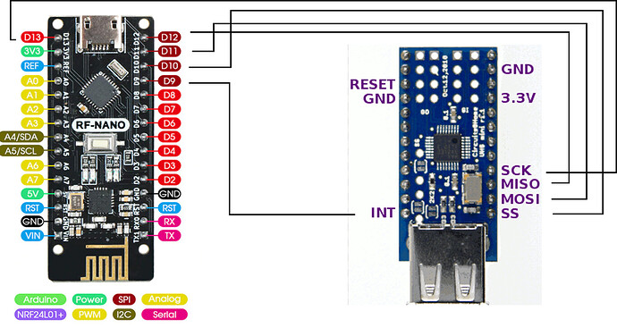
Why have you all the pinMode() lines commented out - those pins need to be set as OUTPUT

I don't see any code that sets SS_PIN_USB LOW and HIGH

...R

I actually looked in the RF24 library which sets the pins to high and low every time I write something to the radio. It also handles the pinmode() stuff when starting the radio. I figured the USB library would do something similar. But I will try including it for the radio.

Robin2:
Why have you all the pinMode() lines commented out - those pins need to be set as OUTPUT

I don't see any code that sets SS_PIN_USB LOW and HIGH

...R

I've added both the pinMode() and the digitalWrite(SS_PIN_USB, LOW) and HIGH. It din't break the code, but also didn't help. The controller still gets stuck. Even without triggering it it continues to rumble and sending the same value over and over.

mroobbo:
I've added both the pinMode() and the digitalWrite(SS_PIN_USB, LOW) and HIGH. It din't break the code, but also didn't help. The controller still gets stuck. Even without triggering it it continues to rumble and sending the same value over and over.

I'm not sure that I can help any further but if I could see the latest version of your program it would be a big help. The devil is in the detail.

...R

#include <SPI.h>
#include <nRF24L01.h>
#include <RF24.h>

#include <XBOXUSB.h>

// Satisfy the IDE, which needs to see the include statment in the ino too.
#ifdef dobogusinclude
  #include <spi4teensy3.h>
#endif


#define CE_PIN_RADIO  7 //CE : set high to receive wireless data, low to send
#define CSN_PIN_RADIO 8 //Same as SS: SPI enable pin, set low to listen to SPI bus.
//SS Pin USB needs to stay standard (PIN D10) I don't know how to change it
#define SS_PIN_USB 10

int i = 0;

const uint64_t pipe = 0x1; // This is the transmit pipeline
int sendData[1];  // One element array holding our random number

RF24 radio(CE_PIN_RADIO, CSN_PIN_RADIO); // Activate the Radio

USB Usb;
XBOXUSB Xbox(&Usb);

void setup()   
{
  pinMode(CE_PIN_RADIO, OUTPUT);
  pinMode(CSN_PIN_RADIO, OUTPUT);
  pinMode(SS_PIN_USB, OUTPUT);

  Serial.begin(115200); //9600 or 115200
 
  #if !defined(__MIPSEL__)
    while (!Serial); // Wait for serial port to connect - used on Leonardo, Teensy and other boards with built-in USB CDC serial connection
  #endif
 
  if (Usb.Init() == -1) {
    Serial.print(F("\r\nOSC did not start"));
    while (1); //halt
  }
  Serial.print(F("\r\nXBOX USB Library Started"));

  //Start Radio after USB
  radio.begin();
  radio.openWritingPipe(pipe);
  
 
}


void loop()   
{
  digitalWrite(SS_PIN_USB, LOW);
  Usb.Task();
  if (Xbox.Xbox360Connected) {
    //Serial.println("XBOX");
    /*
    if (Xbox.getButtonPress(L2) || Xbox.getButtonPress(R2)) {

      Serial.print("L2: ");
      Serial.print(Xbox.getButtonPress(L2));
      Serial.print("\tR2: ");
      Serial.println(Xbox.getButtonPress(R2));

      sendData[0] = Xbox.getButtonPress(R2);

      Xbox.setRumbleOn(Xbox.getButtonPress(L2), Xbox.getButtonPress(R2));
    } else
      Xbox.setRumbleOn(0, 0);
      */

      Serial.print("L2: ");
      Serial.print(Xbox.getButtonPress(L2));
      Serial.print("\tR2: ");
      Serial.println(Xbox.getButtonPress(R2));

      sendData[0] = Xbox.getButtonPress(R2);
  }
  digitalWrite(SS_PIN_USB, HIGH);

  //sendData[0] = i++;
  
  digitalWrite(CSN_PIN_RADIO, LOW);
  radio.write( sendData, sizeof(sendData)); //Nach dem Write Befehl wird CSN wieder auf HIGH gesetzt (siehe RF24.cpp Zeile 98)
  digitalWrite(CSN_PIN_RADIO, HIGH);

  Serial.println(sendData[0]);
  Serial.println(i++); //To see if the Arduino freezes (doesn't seem to be the case)
  delay(1);


}

Thanks for your afford. The Code is pretty much untouched though... The layout is still as you can see in the latest picture.

You have managed the SS pins as I think they should be managed.

I wonder if it would be worth having a short delay() (maybe 20 msecs) between pulling an SS pin LOW and trying to communicate?

Another thought is that everything is happening very fast - at the speed loop() can repeat. Maybe having a general delay(500) at the end of loop() would be useful for testing.

Another thought is that you only need to use the nRF24 if you have actually received something from the XBox - so maybe the XBox connection should be "live" all of the time except when it is necessary to send an nRF24 message.

Drawing all those thoughts together makes me wonder if you need to consider more carefully how the different parts of the program should operate relative to each other. Many communication problems are due to inadequate logic rather than inadequate code.

...R

I think you need a 3.3V level shifter for the USB host shield.

Whandall:
I think you need a 3.3V level shifter for the USB host shield.

What do you mean by that? I disconnected V_bus from the USB Port, which used to be 3.3V and connected a seperate 5V line to it. So the Shield chips receive 3.3V, but the USB Power is 5V (data lines are 3.3V again)...

mroobbo:
What do you mean by that?

3.3V devices - generally - don't like to receive signals above 3.3V (with a safety margin)
and sometimes have a hard time driving logic that expects a 5V signal.

The NRF24L01 is an exception, it is 5V tolerant.

There are many possibilities to shift the level of the signals,
it's even simpler than usual with SPI which uses only uni-directional lines.

If you want to be on the save side (which also works better), you use some kind of level shifting.

Whandall:
3.3V devices - generally - don't like to receive signals above 3.3V (with a safety margin)
and sometimes have a hard time driving logic that expects a 5V signal.

The NRF24L01 is an exception, it is 5V tolerant.

There are many possibilities to shift the level of the signals,
it's even simpler than usual with SPI which uses only uni-directional lines.

If you want to be on the save side (which also works better), you use some kind of level shifting.

So do I understand it right?
The NRF24L01 and my shield are now receiving 3.3V. Thus also sending 3.3V signals (as high). But the Arduino Nano runs at 5V. Thus expecting 5V as a high input (but also excepts 3.3V)? Is the Arduino than sending 5V as a high signal?

So i should shift the voltage of the signals to the Arduino from 3.3V to 5V and from the Arduino to the boards to 3.3?

mroobbo:
So I should shift the voltage of the signals to the Arduino from 3.3V to 5V and from the Arduino to the boards to 3.3?

You need a shift to 3.3V for the signals going to the USB host chip,
unless its data-sheet tells you otherwise.

The 3.3V signals from the USB host chip may (seem to) work without shifting (now).
You will have a better noise resistance if you shift these signals too.

Some level shifters have an OE pin which helps to isolate misbehaving modules (like some TF modules),
but that is probably not relevant here.

oh okay. that makes a lot of sense now! Thank you so much! I will try it as soon as possible.

One more thing... What does OE stand for and what would I use it for? On one schematic I saw the pin connected to V_low (in this case 3.3V). But I read OE stands for Output Enable and is active LOW?? That doesn't quite make sense to me...

Output Enable allows the device to access the output pins, if inactive those pin will float.

The polarity of the signal is device dependent.

This topic was automatically closed 120 days after the last reply. New replies are no longer allowed.