1. Introduction
Traditional wearable sensing devices such as myoelectric sensors [Reference Tam, Boukadoum, Campeau-Lecours and Gosselin1], inertial sensors [Reference Shaeffer2, Reference Jain, Semwal and Kaushik3], tactile sensing arrays [Reference Shao, Hu and Visell4, Reference Ohka, Takata, Kobayashi, Suzuki, Morisawa and Yussof5], etc. are uncomfortable and inconvenient due to the large size and suffer from high manufacturing cost. With the continuous breakthrough of sensing technology, electronic skin (e-skin) sensors with desired characteristics begin to emerge [Reference Hammock, Chortos, Tee, Tok and Bao6, Reference Yang, Mun, Kwon, Park, Bao and Park7] which significantly improves the performance of sensing devices.
Currently, e-skin is playing an increasingly important role in the emerging field of wearable sensing devices [Reference Yu, Nassar, Xu, Min, Yang, Dai, Doshi, Huang, Song, Gehlhar, Ames and Gao8]. As a new generation of wearable devices, e-skin is featured of flexibility, light weight, comfortable wearing, and strong adhesion. It can not only be integrated into the robotic system to provide rich and diverse information for robot perception, control, and decision-making [Reference Hua, Sun, Liu, Bao, Yu, Zhai, Pan and Wang9] but also be attached to the human body surfaces to provide diagnosis and monitoring capability [Reference Kim, Kim and Lee10]. Furthermore, e-skin can be closely combined with the current artificial intelligence [Reference Lee, Heo, Kim, Eom, Jung, Kim, Kim, Park, Mo, Kim and Park11].
In the field of robotic intelligent perception [Reference Shih, Shah, Li, Thuruthel, Park, Iida, Bao, Kramer-Bottiglio and Tolley12], e-skin has a wide range of application prospects, and there has been some research progress in this field. In ref. [Reference Gu, Zhang, Xu, Lin, Yu, Chai, Ge, Yang, Shao, Sheng, Zhu and Zhao13], a lightweight and soft capacitive e-skin pressure sensor was designed for neuromyoelectric prosthetic hand, which enhanced the speed and dexterity of the prosthetic hand. In ref. [Reference Boutry, Negre, Jorda, Vardoulis, Chortos, Khatib and Bao14], a soft e-skin, consisting of an array of capacitors and capable of real-time detection of normal and tangential forces, was designed for robotics dexterous manipulation of objects. In ref. [Reference Rahiminejad, Parvizi-Fard, Iskarous, Thakor and Amiri15], a biomimetic circuit was developed for e-skin attached to a prosthetic hand, which allows the prosthetic hand to sense edge stimulus in different directions. In ref. [Reference Liu, Yiu, Song, Huang, Yao, Wong, Zhou, Zhao, Huang, Nejad, Wu, Li, He, Guo, u, Feng, Xie and Yu16], an e-skin integrated with solar cells was developed for proximity sensing and touch recognition in robotic hand. In ref. [Reference Lee, Son, Lee, Kim, Kim, Nguyen, Lee and Cho17], a multimodal e-skin was developed for robotic prosthesis, with sensors capable of simultaneously recognizing materials and textures. However, some current researches focus more on the sensor itself [Reference Liu, Yiu, Song, Huang, Yao, Wong, Zhou, Zhao, Huang, Nejad, Wu, Li, He, Guo, u, Feng, Xie and Yu16, Reference Lee, Son, Lee, Kim, Kim, Nguyen, Lee and Cho17], ignoring the importance of the signal acquisition and analysis. In addition, the e-skin only has a single dimension [Reference Chen, Khamis, Birznieks, Lepora and Redmond18] and acquires little information. Therefore, it is necessary to consider not only the performance of the e-skin, but also the efficiency of signal acquisition.
Besides the intelligent perception of robots, another potential application field of e-skin is human-related health detection and human-machine interaction (HMI) [Reference Jiang, Li, Xu, Xu, Gu and Shull19–Reference Liu, Yiu, Song, Huang, Yao, Wong, Zhou, Zhao, Huang, Nejad, Wu, Li, He, Guo, Yu, Feng and Xie24]. In ref. [Reference Jiang, Li, Xu, Xu, Gu and Shull19], a stretchable e-skin patch was designed for gesture recognition, and high recognition accuracy was achieved. In ref. [Reference Tang, Shang and Jiang20], a highly stretchable multilayer electronic tattoo was designed to realize many applications such as temperature regulation, motion monitoring, and robot remote control. In ref. [Reference Sundaram, Kellnhofer, Li, Zhu, Torralba and Matusik21], a flexible and stretchable tactile glove and deep convolutional neural networks were used to identify grasped objects and estimate object weight. In ref. [Reference Gao, Emaminejad, Nyein, Challa, Chen, Peck, Fahad, Ota, Shiraki, Kiriya, Lien, Brooks, Davis and Javey22], a flexible and highly integrated e-skin sensor array was designed for sweat detection, which integrated the functions of signal detection, wireless transmission and processing. In ref. [Reference Li, Liu, Xu, Wang, Shu, Sun, Tang and Wang23], a stretch-sensing device with grating-structured triboelectric nanogenerator was designed to detect the bending or stretching of the spinal, which was helpful for human joint health detection. In ref. [Reference Liu, Yiu, Song, Huang, Yao, Wong, Zhou, Zhao, Huang, Nejad, Wu, Li, He, Guo, Yu, Feng and Xie24], an e-skin with both sensing and feedback functions was developed for applications such as robotic teleoperation, robotic virtual reality, robotic healthcare, etc. In some existing applications [Reference Jiang, Li, Xu, Xu, Gu and Shull19, Reference Li, Liu, Xu, Wang, Shu, Sun, Tang and Wang23], more focus is on the analysis of sensor signals, and there are relatively few real-time applications. Meanwhile, some simple applications of e-skin [Reference Liu, Yiu, Song, Huang, Yao, Wong, Zhou, Zhao, Huang, Nejad, Wu, Li, He, Guo, Yu, Feng and Xie24] lack in-depth analysis and understanding of sensor signals.
To solve the problems of e-skin sensor mentioned above, a wearable e-skin sensing system with the characteristics of lightness, portability, scalability, and adhesion is developed for robotic hand teleoperation in this paper. Unlike some e-skins mentioned earlier, our designed e-skin sensing system integrates efficient sensing, transmission, and processing functions at the same time. First, the fabrication method of e-skin sensor in detail is introduced. Then, a flexible printed circuit (FPC) with small size and low-power consumption is specially customized for effective signal acquisition. The designed FPC wirelessly transmits the data to the remote computer through the WiFi module, and a supporting data display and saving interface based on Qt framework are developed. Next, based on the developed wearable e-skin device, we conduct recognition experiments on 9 types of gesture actions using deep learning techniques. Finally, based on the self-developed 2-DOF robotic hand platform, robotic hand teleoperation experiment is carried out to demonstrate the novelty and potential of the e-skin.
2. E-skin sensor design
The structure of human fingers is delicate and complex, which is a multi-joint system composed of multiple bones. According to the classification of physiological anatomy [Reference Miyata, Kouchi and Kurihara25], the human index finger, middle finger, ring finger, and little finger are similar in structure, which are all composed of three phalanges and one metacarpal bone, while the thumb is composed of two phalanges and one metacarpal bone. The bones are connected through different joints, and the movement of joints contains rich information. Therefore, effective monitoring of joint activities will help to the decoding of hand postures. In this section, we present a design scheme of a multi-channel e-skin sensor for the extraction of hand feature information, including the design principle of e-skin, the manufacturing process of e-skin, and the preliminary test of e-skin.
2.1. E-skin design principle
To fully exploit the potential of e-skin in extracting motion information, a stretchable sensor that fits completely on the skin surface is designed. This sensor consists of 11-channel stretchable resistors attached to the major joints of the fingers and the skin surface, as shown in Fig. 1(a). The resistors 1–10 are distributed at the proximal and metacarpal joints of each finger, respectively, and resistor 11 is distributed at the purlicue. Carbon nanotubes are used as the fabrication material for stretchable resistors.
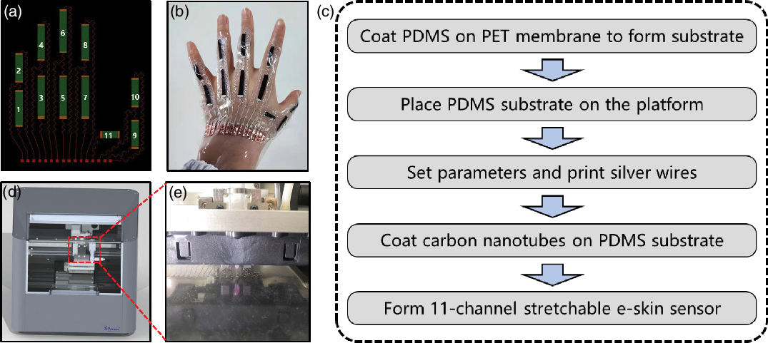
Figure 1. (a) Schematic diagram of e-skin sensor. (b) Wearing diagram of e-skin sensor. (c) Overall manufacturing process of stretchable e-skin sensor. (d, e) Physical drawing of DB100 microelectronic printer.
2.2. E-skin fabrication scheme
For the e-skin sensor fabrication, a microelectronic printer DB100 from Shanghai Mifang Electronic Technology Co., Ltd is used to print the structure.
The design can be divided into the following steps:
The Polydimethylsiloxane (PDMS) is coated on the Polyethylene (PET) membrane and dried in the drying box to form the PDMS substrate.
The fabricated PDMS substrate is neatly placed on the operation platform of DB100 printing electronic multifunction printer, as shown in Fig. 1(d), (e).
The printing parameters are properly set using the DB100 supporting software to print and draw silver wires on the PDMS substrate.
Finally, carbon nanotubes with a concentration of 5% on the stretchable silica gel are uniformly spread on the PDMS substrate by template printing, and 11-channel stretchable e-skin is formed.
The overall fabrication process is shown in Fig. 1(c), and the final fabricated e-skin sensor is shown in Fig. 1(b).
2.3. Performance test of e-skin
After the manufacturing of e-skin, it is necessary to test the stretching and electrical properties of e-skin sensor. Here, we choose to test the stretching resistance of a single channel (the characteristics of other channels are similar). The stretching property of the sensor is tested by Instron 5565 (Instron 5565, Instron (Shanghai) LTD., USA), and the stretching ratio is set to 150%. In addition, the electrical performance of the sensor is detected and output by Keithley (DMM7510, Tektronix). The final cyclic stretching result is shown in Fig. 2. The sensor unit can maintain a relatively stable state under a large number of repeated stretching conditions.
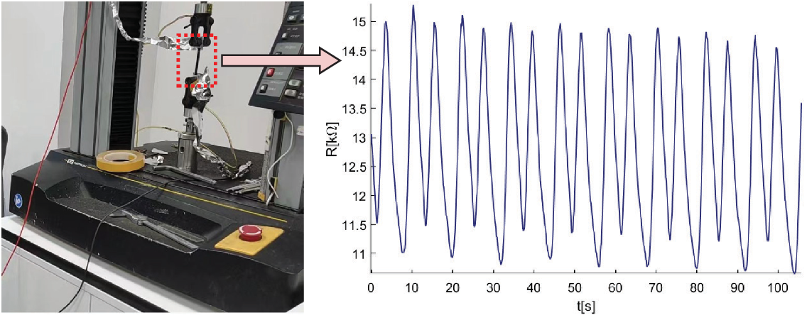
Figure 2. Graph of the electrical properties of the e-skin under cyclic stretching conditions.
3. Wireless transmission interface design
For the e-skin sensor monitoring, we need to customize the data acquisition system to realize the transmission of on-site signal. Wireless external communication plays an important role in the acquisition system, and we choose WiFi as the communication channel. Since traditional printed circuit board is uncomfortable to wear due to its hardness, the scheme of FPC is employed in this work.
3.1. Chip solution selection
The FPC mainly involves the microcontroller unit (MCU), the data wireless transmission module, the power management module, the analog-to-digital conversion (ADC) module, etc., where MCU is the core part. Considering low cost and power consumption, a STM32G431CBT6 chip with LQFP-48 package as the MCU is chosen. This chip has 170 MHz mainstream ARM Cortex-m4 MCU with DSP and FPU, and 128 KB flash memory. At the same time, the built-in ADC modules of STM32 are used to measure the resistance. In addition, it also has abundant peripheral resources such as UART, SPI, Timer, etc., which can fully meet the system requirements.
In order to ensure the reliability and convenience of data transmission, W600-A800, a low-power WiFi chip, is chosen as the data transmission module of our circuit to realize the communication between e-skin sensor and data receiving terminal.
After the selection of MCU and WiFi module, an appropriate power management chip is needed to ensure the normal work of STM32 and WiFi. Here, a widely used rechargeable 3.7 V lithium battery is chosen as the power source. Since the STM32 and WiFi chips need a stable 3.3 V voltage to work properly, a 3.7 V-to-3.3 V chip RT9013-33 is selected to generate 3.3 V voltage. For the convenience of calculation, the TL431 chip is used to output a stable 3 V voltage as the reference voltage to the ADC modules.
3.2. Circuit schematic design
The developed 11-channel resistors of e-skin sensor are measured based on two built-in ADCs in STM32. The overall circuit connection and measurement principle are shown in Fig. 3(a). Here, the resistors are connected in a voltage-dividing manner, and a reference resistor is connected in series with the resistor to be measured for each channel. Since the built-in ADC is 12-bit, its maximum reading value is 4095, corresponding to a 3 V voltage. Thus, the resistance value of each channel can be obtained:
where
![]() $ R_c$
represents the resistance of each stretchable resistor,
$ R_c$
represents the resistance of each stretchable resistor,
![]() $ R_f$
represents the reference resistance welded on the FPC, and
$ R_f$
represents the reference resistance welded on the FPC, and
![]() $V_{\textrm{adc}}$
represents the reading value of the built-in ADC.
$V_{\textrm{adc}}$
represents the reading value of the built-in ADC.

Figure 3. (a) Circuit connection and signal transmission diagram. (b) Overview of the designed FPC.
The circuit schematic diagram of the e-skin monitoring unit is then designed based on above analysis. In addition to the basic chip interface, the SWD interface for program debugging and the sensor interface for connecting the e-skin are reserved. Finally, the physical diagram of the circuit after the welding test is shown in Fig. 3(b).
3.3. Acquisition circuit programming
In order to realize the real-time measurement of e-skin sensor by the designed FPC, the STM32CubeMx software is used to develop specific programs. The configuration of STM32CubeMx software mainly includes the following steps: First, the MCU corresponding to the STM32 is selected and its clock is configured. The clock frequency of all peripheral devices uses the default 170 MHz. The initialization parameters of peripheral modules, such as UART, ADC, Timer, are then configured. Among them, the baud rate of the UART is configured as 115200 for connecting to the WiFi chip, and the two ADCs are configured as multi-channel scan query mode.
To achieve efficient transmission and obtain enough observation data, the timing period of the timer is configured as 10ms; that is, the ADC collects a group of data every 10 ms (the acquisition frequency is 100 Hz). In addition, due to the load of network, 10 groups of data are packaged and sent to receiving terminal every 100 ms. This transmission can avoid packet loss and retransmission caused by frequent data transmission, which makes the transmission process reliable and stable. Finally, the initialization project code based on the keil integrated development environment is generated. The overall processing flow is shown in Fig. 4.
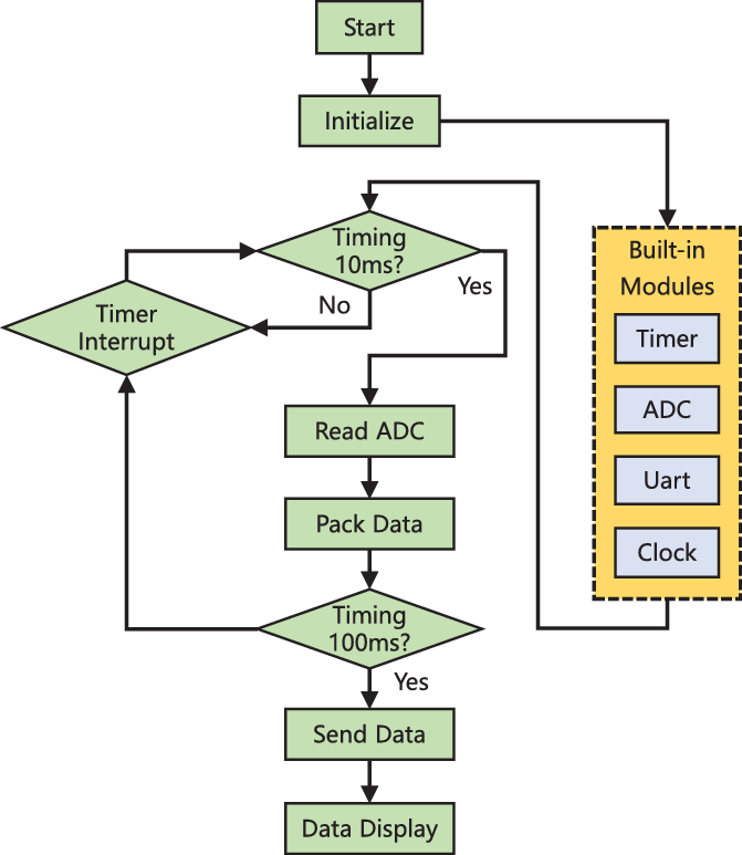
Figure 4. Program flow chart of STM32.
4. Data visualization interface design
In this section, a multi-functional graphical user interface (GUI) based on Qt framework is developed for real-time data interaction, which has multiple functions such as data visualization, multi-process communication, and key operation. In addition, the stability of this GUI in sensor signals processing is also verified by grasping experiments on objects of different shapes and sizes.
4.1. Qt-based GUI design
This GUI consists of three parts: the numerical display, the curve scrolling, and the function buttons, as shown in Fig. 5. The numerical display in the top green box displays the received resistance value in real time, the curve scrolling in the middle red box scrolls and displays the data, and the button under the right bottom includes the control buttons for saving data and enabling WiFi communication.

Figure 5. GUI with data display and save function developed based on Qt framework.
The system requires some configuration, such as IP address, port number, and other network information. Considering that the period of sending data of the FPC is 100ms, and there are 10 groups of measurement values in each period, we take the first group of measurement for display and save all 10 groups of data to the local. In this way, the real-time performance of data transmission is guaranteed.
4.2. Grasp test of different objects
Different gestures of the subjects will lead to the diversity of signals, so that the performance of e-skin system can be verified according to the signal discrimination of different gestures. For verification, we conduct a test in which the subject grasps objects of various sizes and shapes such as hamburger, carton, apple, banana, and water cup.
The obtained grasping test results are shown in Fig. 6. Specifically, for objects of different shapes, such as apple, banana, and water cup, the obtained e-skin response data have obvious differences across multiple channels. In addition, for objects with similar shapes such as apple and hamburger, the obtained grasping response curves are also distinct due to their different sizes. This not only verifies the good performance of e-skin sensor itself but also proves the stability and reliability of the signal acquisition and transmission process.
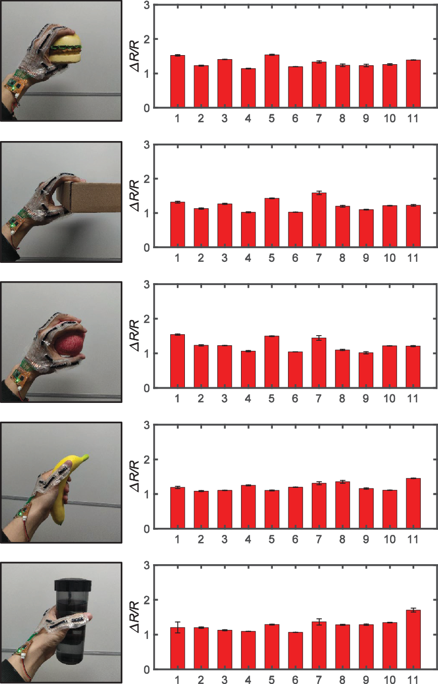
Figure 6. Resistance response ratio of each channel of the e-skin when grasping different objects.
5. Gesture recognition experiments
In this section, we tested and verified the designed e-skin sensing system. Considering that the e-skin adapts to the hand, we design an interactive experiment for gesture recognition according to its characteristics. Since the signals collected by the system belong to time sequence signals, and the data acquisition frequency can reach 100 Hz, and the frequency of sending data is set to 10 Hz, deep learning techniques such as long short-term memory (LSTM) neural network are used to identify such signals. Before the experiment, the acquired raw signals are preprocessed.
5.1. Signals preprocessing
A sliding window method is used to segment the original signals for constructing training samples and testing samples suitable for LSTM network. For a continuous period of e-skin data, it is intercepted from
![]() $T_1$
ms to
$T_1$
ms to
![]() $T_2$
ms. At this time, the amount of data obtained on each channel of e-skin is
$T_2$
ms. At this time, the amount of data obtained on each channel of e-skin is
![]() $N$
, and the following relationship is satisfied:
$N$
, and the following relationship is satisfied:
where
![]() $f$
represents the sampling frequency of e-skin by FPC, and its unit is Hz. Assuming that the number of channels is
$f$
represents the sampling frequency of e-skin by FPC, and its unit is Hz. Assuming that the number of channels is
![]() $C$
, the format of obtained original data meets
$C$
, the format of obtained original data meets
![]() $x_{\textrm{sample}} \in{R^{N \times C}}$
.
$x_{\textrm{sample}} \in{R^{N \times C}}$
.

Figure 7. Schematic diagram of sliding window.
After the original data is obtained, sliding window is used to segment the data to construct multiple sub-samples. The specific segmentation method is shown in Fig. 7. Assuming that the length of the sliding window is
![]() $ W$
, the sliding step is
$ W$
, the sliding step is
![]() $ \lambda$
, and the number of sub-samples after segmentation is
$ \lambda$
, and the number of sub-samples after segmentation is
![]() $ L$
, the relationship is:
$ L$
, the relationship is:
where the number of sub-samples of e-skin data can be obtained as
![]() $ L = \left [{\frac{{N - \lambda }}{{W - \lambda }}} \right ]$
, where
$ L = \left [{\frac{{N - \lambda }}{{W - \lambda }}} \right ]$
, where
![]() $ \left [ \cdot \right ]$
represents the largest integer not greater than the number in it. The format of the resulting sub-images is
$ \left [ \cdot \right ]$
represents the largest integer not greater than the number in it. The format of the resulting sub-images is
![]() ${x_{\text{sub-sample}}} \in{R^{W \times C}}$
.
${x_{\text{sub-sample}}} \in{R^{W \times C}}$
.
5.2. LSTM neural network algorithm
LSTM network is a special recurrent neural network (RNN). Ordinary RNN cannot deal with the long-term dependency problem of time sequence signals in practice, while LSTM can deal with the long-term dependency problem due to its special structure. In addition, LSTM networks are currently widely used in speech recognition, machine translation, text generation and other fields. Therefore, this network algorithm is chosen to recognize our e-skin signals.
The basic principle of LSTM neural network is shown in Fig. 8. Its internal mechanism is to regulate the information flow through forget gate, input gate, and output gate. Each LSTM cell has its own unit state
![]() ${c_t}$
, and LSTM uses forget gate and input gate to control the content of the unit state
${c_t}$
, and LSTM uses forget gate and input gate to control the content of the unit state
![]() ${c_t}$
at the current moment.
${c_t}$
at the current moment.
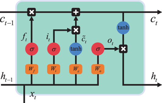
Figure 8. Schematic diagram of LSTM network.
The forget gate determines how much of the unit state
![]() ${c_{t-1}}$
at the previous moment is retained to the current moment
${c_{t-1}}$
at the previous moment is retained to the current moment
![]() ${c_t}$
. The output of the forget gate is:
${c_t}$
. The output of the forget gate is:
where
![]() ${\sigma }$
represents sigmoid activation function,
${\sigma }$
represents sigmoid activation function,
![]() ${W_f}$
is the weight matrix of the forget gate,
${W_f}$
is the weight matrix of the forget gate,
![]() ${h_{t-1}}$
represents the output of the previous moment,
${h_{t-1}}$
represents the output of the previous moment,
![]() ${x_t}$
represents the input of the current moment, and
${x_t}$
represents the input of the current moment, and
![]() ${b_f}$
is the bias term of the forget gate.
${b_f}$
is the bias term of the forget gate.
The input gate determines how much of the input of the network at the current time is retained to the current state
![]() ${c_t}$
, and the output of the input gate is:
${c_t}$
, and the output of the input gate is:
where
![]() ${W_i}$
is the weight matrix of the input gate and
${W_i}$
is the weight matrix of the input gate and
![]() ${b_i}$
is the bias term of the input gate. In addition, the cell state
${b_i}$
is the bias term of the input gate. In addition, the cell state
![]() $\tilde c_t$
describes the current input:
$\tilde c_t$
describes the current input:
where
![]() ${W_c}$
is the weight matrix of the current input, and
${W_c}$
is the weight matrix of the current input, and
![]() ${b_c}$
is the bias term of the current input.
${b_c}$
is the bias term of the current input.
The forget gate, the input gate and the state of the current input
![]() ${\tilde c_t}$
jointly determine the unit state at the current moment
${\tilde c_t}$
jointly determine the unit state at the current moment
![]() ${c_t}$
,
${c_t}$
,
where
![]() $ \circ$
represents vector cross product operation. Through this combination, LSTM adds the current memory to the long-term memory, forming a new memory state
$ \circ$
represents vector cross product operation. Through this combination, LSTM adds the current memory to the long-term memory, forming a new memory state
![]() ${c_t}$
.
${c_t}$
.
Then, the output gate controls the updated memory state, and the output of output gate is:
where
![]() $ W_o$
is the weight matrix of the output gate and
$ W_o$
is the weight matrix of the output gate and
![]() $ b_o$
is the bias term of the output gate. The output of the LSTM unit
$ b_o$
is the bias term of the output gate. The output of the LSTM unit
![]() $ h_t$
is finally determined by the output gate
$ h_t$
is finally determined by the output gate
![]() $ o_t$
and the new memory
$ o_t$
and the new memory
![]() $ c_t$
:
$ c_t$
:
5.3. Experimental scheme
To verify the potential of the developed e-skin, we design multiple gesture recognition scenes. The gestures dataset in the experiment are divided into static gestures (SG) and dynamic gestures (DG). The SG include four categories, namely, the flex and extend of the index finger and the thumb, and the flex and extend of the remaining three fingers, as shown in Fig. 9: SG1, SG2, SG3, and SG4. The DG include five categories, which are defined as the gestures generated by the continuous movement of the hand. The transformation of gesture state is shown in Fig. 9: DG1, DG2, DG3, DG4 and DG5.

Figure 9. LSTM network structure for five dynamic gestures and four static gestures recognition.
In order to realize the recognition of SG and DG at the same time, we specially design a LSTM network adapted to the e-skin signal to decode different gestures. The structure of the network is shown in Fig. 9. The time step
![]() $ t$
is set to 20, that is, the input data dimension of the network is
$ t$
is set to 20, that is, the input data dimension of the network is
![]() $ 20 \times 11$
, which represents the amount of data of 100 ms. In addition, a 2-layer LSTM network is designed, and a fully connected layer and a softmax layer are set after the last time step. The construction of this network is based on the open source keras deep learning framework.
$ 20 \times 11$
, which represents the amount of data of 100 ms. In addition, a 2-layer LSTM network is designed, and a fully connected layer and a softmax layer are set after the last time step. The construction of this network is based on the open source keras deep learning framework.
A participant, whose back of hand is the same size as the designed e-skin, is involved in the experiment. Then, the participant wears our e-skin to repeat different movements. Finally, based on the designed LSTM network, training and testing are carried out on the constructed samples, and 91.22% recognition accuracy is obtained. The confusion matrix of all movements recognition is shown in Fig. 10.

Figure 10. Confusion matrix diagram for dynamic gesture recognition.
6. Robotic hand teleoperation
To further verify the practical application potential of the e-skin, we have conducted an interaction experiment between robotic hand and human hand based on this e-skin using finite state machine (FSM) algorithm. Specifically, we connect the previously identified SG with the postures of the robotic hand. According to the recognition result, the robotic hand can complete the corresponding actions and accurately switch between different states. In this way, the participants can realize the remote operation and effective control of robotic hand.
6.1. Robotic hand platform
We have independently developed a multi-fingered hand platform. The specific internal structure of the robotic hand is shown in Fig. 11(a). This robotic hand has 2 degrees of freedom. The index finger and thumb can be flexed and extended at the same time, as can the remaining three fingers. They are driven by 5 W and 2 W motor, respectively. In addition, the force-bearing parts of the robotic hand are made of aluminum, and the shell is made of 3D-printed resin material. Such a design not only enables strong mechanical properties but also reduces its weight.

Figure 11. (a) Internal structure of the robotic hand. (b) Implementation diagram of robotic hand teleoperation.
6.2. FSM based robotic teleoperation
To completely match the previous gesture recognition results, we consider the four postures POS1, POS2, POS3, and POS4 of the robotic hand with the SG SG1, SG2, SG3, and SG4. DG are used as a priori for static gesture transformations to prevent misoperations caused by misrecognition. The mapping state transition diagram of the robotic hand posture and gesture dataset is shown in Fig. 12. The robotic hand adopts PD-based position control.
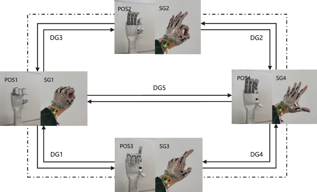
Figure 12. State transition diagram of gestures and robotic hand.
The specific implementation of the robotic teleoperation is shown in Fig. 11(b), which is mainly divided into the following steps:
The WiFi communication between the e-skin sensor terminal and Qt-based HMI software terminal is established to ensure that HMI software terminal can collect signals in real time.
The socket communication between the HMI software and the signal processing terminal in python is established. Then, the pre-trained LSTM classification model is loaded in advance, and the online recognition and analysis of gesture signals are performed.
Finally, the socket communication between the HMI software and the MFC-based control terminal is established, and the recognition results are transmitted to the robot to realize the state switching and follow-up of the robot.
We select SG1 as the initial gesture state and then test the state following performance of the e-skin wearer in the order of SG1-SG2-SG4-SG3-SG1-SG4-SG1. After several tests, the robotic hand can effectively follow the gestures to switch states, and the average switching delay is less than 1s. In addition, the false recognition rate is low, and barely false actions of the robotic hand are identified.
When the robotic fingers are in the open or closed state, the relative positions of the driving motors are defined as 0 and 1, respectively. After the experimental tests, the position displacements of the driving motors during the state switching are shown in Fig. 13. Figure 13 shows that the developed robotic hand has good position control and can move the corresponding position rapidly.

Figure 13. The position displacements of the driving motors in different states.
7. Discussion and conclusions
This paper has developed a stretchable and portable e-skin sensing system including e-skin sensor, FPC with WiFi communication function, and human-machine interface. The e-skin sensor can be attached to the opisthenar to detect the fingers’ flexion and extension. The FPC acquire the sensor signals and then wirelessly transmits to the terminal device with our developed human-machine interface for data processing.
LSTM neural network algorithm is used to test the collected e-skin signals and achieves 91.22% recognition accuracy on 9 kinds of DG. Unlike conventional visual sensors, the e-skin is not affected by light and environment, which is superior to traditional vision sensors in terms of cost and recognition stability. Based on the pre-trained LSTM network model, we conduct robotic hand teleoperation experiments using FSM, which validates the application potential of the developed e-skin for efficient control of robotic hand poses.
In future, we will analyze the mechanical and electrical properties of the developed e-skin sensor in detail. In addition, we will try to optimize the performance of this sensor and explore the relationship between the deformation of the e-skin and the flex of the fingers.
Acknowledgements
This work was supported in part by the Strategic Priority Research Program of the Chinese Academy of Sciences under Grant XDA16021200, in part by the National Natural Science Foundation of China under Grant 62133013 and Grant U1913601, and in part by the National Key Research and Development Program of China under Grant 2018AAA0102900 and Grant 2021YFF0501600.
Authors’ contributions
All the authors have made great contributions to this paper.
Conflicts of interest
The authors declare none.


