74LS244 Datasheet
74LS244 Datasheet
74LS244 Datasheet
Create successful ePaper yourself
Turn your PDF publications into a flip-book with our unique Google optimized e-Paper software.
SN54LS240, SN54LS241, SN54LS244, SN54S240, SN54S241, SN54S244SN74LS240, SN74LS241, SN<strong>74LS244</strong>, SN74S240, SN74S241, SN74S244OCTAL BUFFERS AND LINE DRIVERS WITH 3-STATE OUTPUTSSDLS144B – APRIL 1985 – REVISED FEBRUARY 2002switching characteristics, V CC = 5 V, T A = 25°C (see Figure 2)PARAMETERTEST CONDITIONS’S240 ’S241, ’S244MIN TYP MAX MIN TYP MAXUNITtPLHtPHLRL =90Ω Ω,CL = 50 pF4.5 7 6 94.5 7 6 9nstPZLtPZHRL =90Ω Ω,CL = 50 pF10 15 10 156.5 10 8 12nstPLZtPHZRL = 90 Ω,CL = 5 pF10 15 10 156 9 6 9nsPOST OFFICE BOX 655303 • DALLAS, TEXAS 752659
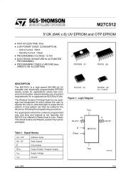
SN54LS240, SN54LS241, SN54LS244, SN54S240, SN54S241, SN54S244SN74LS240, SN74LS241, SN<strong>74LS244</strong>, SN74S240, SN74S241, SN74S244OCTAL BUFFERS AND LINE DRIVERS WITH 3-STATE OUTPUTSSDLS144B – APRIL 1985 – REVISED FEBRUARY 2002PARAMETER MEASUREMENT INFORMATIONSERIES 54LS/74LS DEVICESFrom OutputUnder TestTestPointCL(see Note A)VCCRL(see Note B)From OutputUnder TestCL(see Note A)VCCRLTestPointVCCFrom OutputUnder TestCL(see Note A)TestPointRL5 kΩS1(see Note B)S2LOAD CIRCUITFOR 2-STATE TOTEM-POLE OUTPUTSLOAD CIRCUITFOR OPEN-COLLECTOR OUTPUTSLOAD CIRCUITFOR 3-STATE OUTPUTSHigh-LevelPulseLow-LevelPulse1.3 V 1.3 Vtw1.3 V 1.3 VVOLTAGE WAVEFORMSPULSE DURATIONSTimingInputDataInputtsu1.3 Vth1.3 V 1.3 VVOLTAGE WAVEFORMSSETUP AND HOLD TIMES3 V0 V3 V0 VInput1.3 V 1.3 V3 V0 VOutputControl(low-levelenabling)tPZL1.3 V 1.3 VtPLZ3 V0 VIn-PhaseOutput(see Note D)Out-of-PhaseOutput(see Note D)tPLHtPHLVOLTAGE WAVEFORMSPROPAGATION DELAY TIMEStPHL1.3 V 1.3 VtPLH1.3 V 1.3 VVOHVOLVOHVOLWaveform 1(see Notes Cand D)Waveform 2(see Notes Cand D)NOTES: A. CL includes probe and jig capacitance.B. All diodes are 1N3064 or equivalent.C. Waveform 1 is for an output with internal conditions such that the output is low except when disabled by the output control.Waveform 2 is for an output with internal conditions such that the output is high except when disabled by the output control.D. S1 and S2 are closed for tPLH, tPHL, tPHZ, and tPLZ; S1 is open and S2 is closed for tPZH; S1 is closed and S2 is open for tPZL.E. Phase relationships between inputs and outputs have been chosen arbitrarily for these examples.F. All input pulses are supplied by generators having the following characteristics: PRR ≤ 1 MHz, ZO ≈ 50 Ω, tr ≤ 15 ns, tf ≤ 6 ns.G. The outputs are measured one at a time with one input transition per measurement.tPZH1.3 VFigure 1. Load Circuits and Voltage Waveforms1.3 VVOL + 0.3 VVOLtPHZ≈1.5 VVOHVOH – 0.3 V≈1.5 VVOLTAGE WAVEFORMSENABLE AND DISABLE TIMES, 3-STATE OUTPUTS10 POST OFFICE BOX 655303 • DALLAS, TEXAS 75265
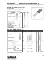
SN54LS240, SN54LS241, SN54LS244, SN54S240, SN54S241, SN54S244SN74LS240, SN74LS241, SN<strong>74LS244</strong>, SN74S240, SN74S241, SN74S244OCTAL BUFFERS AND LINE DRIVERS WITH 3-STATE OUTPUTSSDLS144B – APRIL 1985 – REVISED FEBRUARY 2002PARAMETER MEASUREMENT INFORMATIONSERIES 54S/74S DEVICESFrom OutputUnder TestTestPointCL(see Note A)VCCRL(see Note B)From OutputUnder TestCL(see Note A)VCCRLTestPointVCCFrom OutputUnder TestCL(see Note A)TestPointRL1 kΩS1(see Note B)S2LOAD CIRCUITFOR 2-STATE TOTEM-POLE OUTPUTSLOAD CIRCUITFOR OPEN-COLLECTOR OUTPUTSLOAD CIRCUITFOR 3-STATE OUTPUTSHigh-LevelPulseLow-LevelPulse1.5 V 1.5 Vtw1.5 V 1.5 VVOLTAGE WAVEFORMSPULSE DURATIONSTimingInputDataInputtsu1.5 Vth1.5 V 1.5 VVOLTAGE WAVEFORMSSETUP AND HOLD TIMES3 V0 V3 V0 VInput1.5 V 1.5 V3 V0 VOutputControl(low-levelenabling)tPZL1.5 V 1.5 VtPLZ3 V0 VIn-PhaseOutput(see Note D)Out-of-PhaseOutput(see Note D)tPLHtPHLVOLTAGE WAVEFORMSPROPAGATION DELAY TIMEStPHL1.5 V 1.5 VtPLH1.5 V 1.5 VVOHVOLVOHVOLWaveform 1(see Notes Cand D)Waveform 2(see Notes Cand D)tPZH1.5 V1.5 VVOL + 0.5 VVOLtPHZ≈1.5 VVOHVOH – 0.5 V≈1.5 VVOLTAGE WAVEFORMSENABLE AND DISABLE TIMES, 3-STATE OUTPUTSNOTES: A. CL includes probe and jig capacitance.B. All diodes are 1N3064 or equivalent.C. Waveform 1 is for an output with internal conditions such that the output is low except when disabled by the output control.Waveform 2 is for an output with internal conditions such that the output is high except when disabled by the output control.D. S1 and S2 are closed for tPLH, tPHL, tPHZ, and tPLZ; S1 is open and S2 is closed for tPZH; S1 is closed and S2 is open for tPZL.E. All input pulses are supplied by generators having the following characteristics: PRR ≤ 1 MHz, ZO ≈ 50 Ω; tr and tf ≤ 7 ns for Series54/74 devices and tr and tf ≤ 2.5 ns for Series 54S/74S devices.F. The outputs are measured one at a time with one input transition per measurement.Figure 2. Load Circuits and Voltage WaveformsPOST OFFICE BOX 655303 • DALLAS, TEXAS 7526511
SN54LS240, SN54LS241, SN54LS244, SN54S240, SN54S241, SN54S244SN74LS240, SN74LS241, SN<strong>74LS244</strong>, SN74S240, SN74S241, SN74S244OCTAL BUFFERS AND LINE DRIVERS WITH 3-STATE OUTPUTSSDLS144B – APRIL 1985 – REVISED FEBRUARY 2002APPLICATION INFORMATION12 POST OFFICE BOX 655303 • DALLAS, TEXAS 75265
IMPORTANT NOTICETexas Instruments Incorporated and its subsidiaries (TI) reserve the right to make corrections, modifications,enhancements, improvements, and other changes to its products and services at any time and to discontinueany product or service without notice. Customers should obtain the latest relevant information before placingorders and should verify that such information is current and complete. All products are sold subject to TI’s termsand conditions of sale supplied at the time of order acknowledgment.TI warrants performance of its hardware products to the specifications applicable at the time of sale inaccordance with TI’s standard warranty. Testing and other quality control techniques are used to the extent TIdeems necessary to support this warranty. Except where mandated by government requirements, testing of allparameters of each product is not necessarily performed.TI assumes no liability for applications assistance or customer product design. Customers are responsible fortheir products and applications using TI components. To minimize the risks associated with customer productsand applications, customers should provide adequate design and operating safeguards.TI does not warrant or represent that any license, either express or implied, is granted under any TI patent right,copyright, mask work right, or other TI intellectual property right relating to any combination, machine, or processin which TI products or services are used. Information published by TI regarding third–party products or servicesdoes not constitute a license from TI to use such products or services or a warranty or endorsement thereof.Use of such information may require a license from a third party under the patents or other intellectual propertyof the third party, or a license from TI under the patents or other intellectual property of TI.Reproduction of information in TI data books or data sheets is permissible only if reproduction is withoutalteration and is accompanied by all associated warranties, conditions, limitations, and notices. Reproductionof this information with alteration is an unfair and deceptive business practice. TI is not responsible or liable forsuch altered documentation.Resale of TI products or services with statements different from or beyond the parameters stated by TI for thatproduct or service voids all express and any implied warranties for the associated TI product or service andis an unfair and deceptive business practice. TI is not responsible or liable for any such statements.Mailing Address:Texas InstrumentsPost Office Box 655303Dallas, Texas 75265Copyright © 2002, Texas Instruments Incorporated