Nothing Special   »   [go: up one dir, main page]

You seem to have javascript disabled. Please note that many of the page functionalities won't work as expected without javascript enabled.


Wireless Power Transfer: Material, Technologies, and Applications (Closed)

A topical collection in Electronics (ISSN 2079-9292). This collection belongs to the section "Power Electronics".

Viewed by 49925

Editors

Department of Electrical, Computer and Software Engineering, University of Auckland, Auckland, New Zealand
Interests: wireless power transfer; matrix converter; power electronics; renewable energy

E-Mail Website
Guest Editor
Electrical and Computer Engineering, The University of Auckland, Auckland 1023, New Zealand
Interests: wireless power transfer; power electronics; renewable energy
Special Issues, Collections and Topics in MDPI journals

Topical Collection Information

Dear Colleagues,

We would like to invite you to submit original research and review articles to a Special Issue of the journal Electronics on the topic of “Wireless Power Transfer: Material, Technologies, and Applications”.

In recent years, Wireless Power Transfer (WPT) technologies have found many successful applications in Medical Electronics, Consumer Electronics, Internet of Things (IoT), and Electric Vehicles (EV), etc. It is expected that WPT technologies will be widely applied in more commercial products. However, there are many practical challenges ahead to meet the safety and EMC requirements, particularly for long-distance power transfer at high operating frequencies. This Special Issue will include, but is not limited to, the following topics:

  • Inductive Power Transfer (IPT) systems;
  • Capacitive Power Transfer (CPT) systems;
  • Radiative WPT systems;
  • Energy harvesting;
  • Ultrasonic power transfer, laser power transfer, infrared power transfer, etc.;
  • Electromagnetic compatibility (EMC);
  • Foreign object detection (FOD) and living object detection (LOD) technologies;
  • Electromagnetic materials;
  • Sensing and control of WPT systems;
  • Practical design and productization of WPT systems.

Dr. Qi Zhu
Prof. Dr. Aiguo Patrick Hu
Guest Editors

Manuscript Submission Information

Manuscripts should be submitted online at www.mdpi.com by registering and logging in to this website. Once you are registered, click here to go to the submission form. Manuscripts can be submitted until the deadline. All submissions that pass pre-check are peer-reviewed. Accepted papers will be published continuously in the journal (as soon as accepted) and will be listed together on the collection website. Research articles, review articles as well as short communications are invited. For planned papers, a title and short abstract (about 100 words) can be sent to the Editorial Office for announcement on this website.

Submitted manuscripts should not have been published previously, nor be under consideration for publication elsewhere (except conference proceedings papers). All manuscripts are thoroughly refereed through a single-blind peer-review process. A guide for authors and other relevant information for submission of manuscripts is available on the Instructions for Authors page. Electronics is an international peer-reviewed open access semimonthly journal published by MDPI.

Please visit the Instructions for Authors page before submitting a manuscript. The Article Processing Charge (APC) for publication in this open access journal is 2400 CHF (Swiss Francs). Submitted papers should be well formatted and use good English. Authors may use MDPI's English editing service prior to publication or during author revisions.

Keywords

  • inductive power transfer
  • capacitive power transfer
  • ultrasonic power transfer
  • laser power transfer
  • infrared power transfer
  • microwave power transfer
  • energy harvesting

Published Papers (11 papers)

2023

Jump to: 2022, 2021

14 pages, 4364 KiB  
Article
Analysis and Design of a Dual-Frequency Capacitive Power Transfer System to Reduce Coupler Voltage Stress
by Sen Yang, Yao Zhang, Yiming Zhang, Yongchao Wang, Zhulin Wang, Bo Luo and Ruikun Mai
Electronics 2023, 12(6), 1274; https://doi.org/10.3390/electronics12061274 - 7 Mar 2023
Cited by 3 | Viewed by 1717
Abstract
In a capacitive power transfer (CPT) system, the coupling capacitance formed between the coupling plates is very small only in the pF or nF range, which leads to high voltage stress among the coupling plates during energy transmission, which increases the risk of [...] Read more.
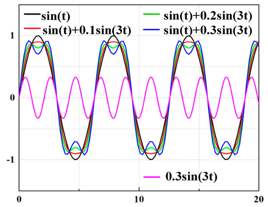
In a capacitive power transfer (CPT) system, the coupling capacitance formed between the coupling plates is very small only in the pF or nF range, which leads to high voltage stress among the coupling plates during energy transmission, which increases the risk of an electrical breakdown between the coupled plates. To solve this problem, a novel dual-frequency CPT system is proposed in this paper, which uses the “peak clipping” effect caused by the superposition of the fundamental wave and third harmonic wave to reduce the voltage stress of the coupled plates. Through the detailed analysis of the working principle of the CPT system, it is shown that the dual-frequency CPT system can indeed reduce the high voltage stress among the coupled plate to 84.3% of the equivalent single-frequency system and can also reduce the inverter conduction losses to 90%. A 200 W prototype is designed with the proposed scheme, and the experimental results confirm the correctness of the theoretical derivation. Full article
Show Figures

Figure 1

Figure 1
<p>The fundamental and third harmonic frequencies’ superimposed wave cluster.</p>
Full article ">Figure 2
<p>(<b>a</b>) Dual-frequency CPT system schematic. (<b>b</b>) Compensation unit model [<a href="#B27-electronics-12-01274" class="html-bibr">27</a>]. (<b>c</b>) Dual-frequency CPT system Π-type equivalent circuit model. (<b>d</b>) Dual-frequency CPT system T-type equivalent circuit model.</p>
Full article ">Figure 3
<p>Relationship between normalized coupler voltage <math display="inline"><semantics> <mrow> <msubsup> <mi>V</mi> <mrow> <mi>m</mi> <mo>,</mo> <mi>d</mi> <mo>,</mo> <mi>m</mi> <mi>a</mi> <mi>x</mi> </mrow> <mo>*</mo> </msubsup> </mrow> </semantics></math> and power-sharing ratio <span class="html-italic">k</span>.</p>
Full article ">Figure 4
<p>Relationship between normalized inverter conduction losses <math display="inline"><semantics> <mrow> <msubsup> <mi>P</mi> <mrow> <mi>i</mi> <mi>n</mi> <mi>l</mi> <mi>o</mi> <mi>s</mi> <mi>s</mi> <mo>,</mo> <mi>d</mi> </mrow> <mo>*</mo> </msubsup> </mrow> </semantics></math> and power-sharing ratio <math display="inline"><semantics> <mi>k</mi> </semantics></math>.</p>
Full article ">Figure 5
<p>Design flowchart of the dual-frequency CPT system.</p>
Full article ">Figure 6
<p>Experimental prototype of the proposed CPT system.</p>
Full article ">Figure 7
<p>Experimental prototype of the proposed CPT system.</p>
Full article ">Figure 8
<p>Waveforms of input voltage <math display="inline"><semantics> <mrow> <msub> <mi>v</mi> <mrow> <mi>i</mi> <mi>n</mi> </mrow> </msub> </mrow> </semantics></math>, input current <math display="inline"><semantics> <mrow> <msub> <mi>i</mi> <mrow> <mi>i</mi> <mi>n</mi> </mrow> </msub> </mrow> </semantics></math>, coupler voltage <math display="inline"><semantics> <mrow> <msub> <mi>v</mi> <mi>m</mi> </msub> </mrow> </semantics></math>, and output current <math display="inline"><semantics> <mrow> <msub> <mi>i</mi> <mrow> <mi>o</mi> <mi>u</mi> <mi>t</mi> </mrow> </msub> </mrow> </semantics></math> for the dual-frequency CPT system in the (<b>a</b>) simulation test and (<b>b</b>) experimental test.</p>
Full article ">Figure 9
<p>Waveforms of (<b>a</b>) the coupler voltage <math display="inline"><semantics> <mrow> <msub> <mi>v</mi> <mi>m</mi> </msub> </mrow> </semantics></math> and (<b>b</b>) inverter output current <math display="inline"><semantics> <mrow> <msub> <mi>i</mi> <mrow> <mi>i</mi> <mi>n</mi> </mrow> </msub> </mrow> </semantics></math> for the proposed dual-frequency system and the equivalent single-frequency system.</p>
Full article ">Figure 10
<p>System output power and efficiency versus <math display="inline"><semantics> <mrow> <msub> <mi>V</mi> <mrow> <mi>d</mi> <mi>c</mi> </mrow> </msub> </mrow> </semantics></math>.</p>
Full article ">Figure 11
<p>Waveforms of input voltage <math display="inline"><semantics> <mrow> <msub> <mi>v</mi> <mrow> <mi>i</mi> <mi>n</mi> </mrow> </msub> </mrow> </semantics></math>, input current <math display="inline"><semantics> <mrow> <msub> <mi>i</mi> <mrow> <mi>i</mi> <mi>n</mi> </mrow> </msub> </mrow> </semantics></math>, coupler voltage <math display="inline"><semantics> <mrow> <msub> <mi>v</mi> <mi>m</mi> </msub> </mrow> </semantics></math>, and output current <math display="inline"><semantics> <mrow> <msub> <mi>i</mi> <mrow> <mi>o</mi> <mi>u</mi> <mi>t</mi> </mrow> </msub> </mrow> </semantics></math> after adding the rectifier structure.</p>
Full article ">Figure 12
<p>The transformation from original load to multiple harmonics model.</p>
Full article ">
2022

Jump to: 2023, 2021

11 pages, 7611 KiB  
Article
A Coaxial and Coplanar Wireless Slipring for Multi-Axis Robot Manipulators
by Lin Chai, Chun Song and Jianghua Lu
Electronics 2022, 11(15), 2352; https://doi.org/10.3390/electronics11152352 - 28 Jul 2022
Cited by 1 | Viewed by 1779
Abstract
This manuscript proposed a compact slipring based on inductive power transfer (IPT) technology for multi-axis robot manipulators. Compared with conventional solutions, the minimum axial length of the proposed magnetic coupling assembly in the IPT based slipring makes it possible to integrate in-robot joint [...] Read more.
This manuscript proposed a compact slipring based on inductive power transfer (IPT) technology for multi-axis robot manipulators. Compared with conventional solutions, the minimum axial length of the proposed magnetic coupling assembly in the IPT based slipring makes it possible to integrate in-robot joint actuators (electrical motors) with high power and torque densities. Additionally, the voltage transfer characteristic of the wireless slipring system is investigated to provide stable and reliable output voltage in the presence of arbitrary motor speeds and load conditions. A 100-W slipring prototype is designed for a practical three-axis robot arm. The simulation and experimental results clearly verify the system feasibility and effectiveness. The maximum efficiency of 90.3% at an 800 kHz operating frequency is achieved. Full article
Show Figures

Figure 1

Figure 1
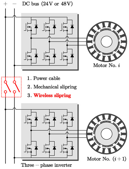
<p>The methods of transferring electrical power between different robot joint actuators, e.g., power cable, mechanical slipring, and wireless slipring.</p>
Full article ">Figure 2
<p>Conventional wireless sliprings. (<b>a</b>) Coaxial, (<b>b</b>) face-to-face, and (<b>c</b>) sandwiched layout.</p>
Full article ">Figure 3
<p>The proposed IPT-based wireless slipring system.</p>
Full article ">Figure 4
<p>3D FEM model of the proposed wireless slipring.</p>
Full article ">Figure 5
<p>(<b>a</b>) An IPT-based slipring with SS compensation topology and (<b>b</b>) its equivalent circuit.</p>
Full article ">Figure 6
<p>The prototype of the proposed wireless slipring. (<b>a</b>) vertical view and (<b>b</b>) left view.</p>
Full article ">Figure 7
<p>The measured <math display="inline"><semantics> <mrow> <msub> <mi>L</mi> <mi>p</mi> </msub> </mrow> </semantics></math>, <math display="inline"><semantics> <mrow> <msub> <mi>L</mi> <mi>s</mi> </msub> </mrow> </semantics></math>, and <math display="inline"><semantics> <mi>k</mi> </semantics></math> of the IPT coupler.</p>
Full article ">Figure 8
<p>Experimental waveforms of the input voltage <math display="inline"><semantics> <mrow> <msub> <mi>v</mi> <mrow> <mi>A</mi> <mi>B</mi> </mrow> </msub> <mrow> <mo>(</mo> <mi>t</mi> <mo>)</mo> </mrow> </mrow> </semantics></math>, input current <math display="inline"><semantics> <mrow> <msub> <mi>i</mi> <mrow> <mi>A</mi> <mi>B</mi> </mrow> </msub> <mrow> <mo>(</mo> <mi>t</mi> <mo>)</mo> </mrow> </mrow> </semantics></math>, output voltage <math display="inline"><semantics> <mrow> <msub> <mi>v</mi> <mrow> <mi>a</mi> <mi>b</mi> </mrow> </msub> <mrow> <mo>(</mo> <mi>t</mi> <mo>)</mo> </mrow> </mrow> </semantics></math>, and output current <math display="inline"><semantics> <mrow> <msub> <mi>i</mi> <mrow> <mi>a</mi> <mi>b</mi> </mrow> </msub> <mrow> <mo>(</mo> <mi>t</mi> <mo>)</mo> </mrow> </mrow> </semantics></math> when the system operates at the rated power.</p>
Full article ">Figure 9
<p>Measured efficiency from DC power source to load by power analyzer.</p>
Full article ">Figure 10
<p>Measured efficiency and output voltage of the IPT system.</p>
Full article ">Figure 11
<p>Dynamic behavior of the IPT-based slipring with different output powers.</p>
Full article ">Figure 12
<p>(<b>a</b>) Two-axis robot arm and (<b>b</b>) its circuit model.</p>
Full article ">Figure 13
<p>(<b>a</b>) Experimental waveforms of <math display="inline"><semantics> <mrow> <msub> <mi>v</mi> <mrow> <mi>A</mi> <mi>B</mi> </mrow> </msub> <mrow> <mo>(</mo> <mi>t</mi> <mo>)</mo> </mrow> </mrow> </semantics></math>, <math display="inline"><semantics> <mrow> <msub> <mi>i</mi> <mrow> <mi>A</mi> <mi>B</mi> </mrow> </msub> <mrow> <mo>(</mo> <mi>t</mi> <mo>)</mo> </mrow> </mrow> </semantics></math>, <math display="inline"><semantics> <mrow> <msub> <mi>v</mi> <mrow> <mi>a</mi> <mi>b</mi> </mrow> </msub> <mrow> <mo>(</mo> <mi>t</mi> <mo>)</mo> </mrow> </mrow> </semantics></math>, and <math display="inline"><semantics> <mrow> <msub> <mi>i</mi> <mrow> <mi>a</mi> <mi>b</mi> </mrow> </msub> <mrow> <mo>(</mo> <mi>t</mi> <mo>)</mo> </mrow> </mrow> </semantics></math>, and (<b>b</b>) the system efficiency of the two-axis robot arm.</p>
Full article ">Figure 14
<p>(<b>a</b>) 3D structure and (<b>b</b>) experimental prototype of the three-axis robot manipulator.</p>
Full article ">
14 pages, 5242 KiB  
Article
Design and Analysis of Magnetic Shielding Mechanism for Wireless Power Transfer System Based on Composite Materials
by Xin Zhang, Rongmei Han, Fangzhou Li, Xuetong Pan and Zhiqi Chu
Electronics 2022, 11(14), 2187; https://doi.org/10.3390/electronics11142187 - 12 Jul 2022
Cited by 9 | Viewed by 2528
Abstract
In a wireless power transfer (WPT) system, in order to reduce the leakage of the magnetic field in the space and to improve the transmission efficiency of the system, a magnetic shielding mechanism is usually added to the coupling coil. However, the commonly [...] Read more.
In a wireless power transfer (WPT) system, in order to reduce the leakage of the magnetic field in the space and to improve the transmission efficiency of the system, a magnetic shielding mechanism is usually added to the coupling coil. However, the commonly used ferrite material has defects of brittleness, easy cracking, and a low saturation limit. Therefore, a novel magnetic shielding mechanism based on a quartz fiber and nanocrystalline reinforced resin matrix composite material was proposed, and epoxy resin and cross-laminate-splicing processes were used to improve the resistivity of the nanocrystalline material and to improve the eddy current loss. A discretized geometric model was designed for quartz fiber, and the effects of different shielding structures on the space magnetic field and the power loss were simulated and analyzed. In the experiment, a space magnetic field measurement system was built, and the transmission efficiency was analyzed. The results showed that the new magnetic shielding mechanism has a good shielding effect, can effectively suppress leakage of the magnetic field in space, reduce the weight, and improve the mechanical performance while also achieving a high transmission efficiency of 85.6%. Full article
Show Figures

Figure 1

Figure 1
<p>Equivalent circuit diagram of S/S-compensated WPT system.</p>
Full article ">Figure 2
<p>Nanocrystalline staggered lamination splicing process.</p>
Full article ">Figure 3
<p>Coupling mechanism of WPT.</p>
Full article ">Figure 4
<p>Quartz fiber discretization simulation model.</p>
Full article ">Figure 5
<p>Simulation results of magnetic field distribution in <span class="html-italic">x–z</span> plane of ferrite shield: (<b>a</b>) transmitting side and (<b>b</b>) receiving side.</p>
Full article ">Figure 6
<p>Simulation results of magnetic field distribution in <span class="html-italic">x–z</span> plane of composite material shielding: (<b>a</b>) transmitting side and (<b>b</b>) receiving side.</p>
Full article ">Figure 7
<p>Simulation results of spatial magnetic field distribution in <span class="html-italic">x–y</span> plane: (<b>a</b>) ferrite shield and (<b>b</b>) composite material shield.</p>
Full article ">Figure 8
<p>The magnetic flux density distribution on the <span class="html-italic">y</span>-axis direction.</p>
Full article ">Figure 9
<p>Comparison of power losses of different shields at 2 KW.</p>
Full article ">Figure 10
<p>Quartz fiber and nanocrystalline reinforced resin matrix composite material.</p>
Full article ">Figure 11
<p>Experiment platform.</p>
Full article ">Figure 12
<p>Magnetic flux density distribution at the measurement line.</p>
Full article ">Figure 13
<p>Shielding effectiveness at the measurement line.</p>
Full article ">Figure 14
<p>Efficiency measurements: (<b>a</b>) inter-coil efficiency and (<b>b</b>) overall efficiency of the system.</p>
Full article ">
15 pages, 5830 KiB  
Article
Analysis and Design of an S/PS−Compensated WPT System with Constant Current and Constant Voltage Charging
by Lin Yang, Zhi Geng, Shuai Jiang and Can Wang
Electronics 2022, 11(9), 1488; https://doi.org/10.3390/electronics11091488 - 6 May 2022
Cited by 6 | Viewed by 2625
Abstract
In recent years, more and more scholars have paid attention to the research of wireless power transfer (WPT) technology, and have achieved a lot of results. In practical charging application, ensuring that the WPT system can achieve constant current and constant voltage output [...] Read more.
In recent years, more and more scholars have paid attention to the research of wireless power transfer (WPT) technology, and have achieved a lot of results. In practical charging application, ensuring that the WPT system can achieve constant current and constant voltage output with zero phase angle (ZPA) operation is very important to prolong battery life and improve power transfer efficiency. This paper proposes an series/parallel series(S/PS)-compensated WPT system that can charge the battery load in constant current and constant voltage modes at two different frequency points through frequency switching. The proposed S/PS structure contains only three compensation capacitors, few compensation elements, simple structure, low economic cost, in addition, the secondary-side does not contain compensation inductor, ensuring the compactness of the secondary-side. An experimental prototype with an input voltage of 40 V is established, and the experiment proves that the model can obtain output voltage of 48 V and current of 2 A. Maximum system transmission efficiency of up to 92.48% The experimental results are consistent with the theoretical analysis results, which verifies the feasibility of the method. Full article
Show Figures

Figure 1

Figure 1
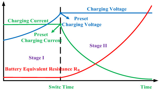
<p>Typical charging profile of the Li-ion battery.</p>
Full article ">Figure 2
<p>Circuit diagram of the S/PS−compensated WPT System.</p>
Full article ">Figure 3
<p>Equivalent circuit of the S/PS−compensated WPT System.</p>
Full article ">Figure 4
<p>Design approaches of the S/PS−compensated WPT system.</p>
Full article ">Figure 5
<p>Experimental model of the loosely coupled transformer.</p>
Full article ">Figure 6
<p>Voltage gain and phase of input impedance of the S/PS−compensated WPT system.</p>
Full article ">Figure 7
<p>Transconductance gain and phase of input impedance of the S/PS−compensated WPT system.</p>
Full article ">Figure 8
<p>Switch strategy of the S/PS−compensated WPT system.</p>
Full article ">Figure 9
<p>Experimental model of the S/PS−compensated WPT system.</p>
Full article ">Figure 10
<p>Experimental waveforms of <b><span class="html-italic">U</span></b><sub>P</sub>, <b><span class="html-italic">I</span></b><sub>P</sub> and <span class="html-italic">I</span><sub>RL</sub> in CC charging mode. (<b>a</b>) <span class="html-italic">R</span><sub>L</sub> = 5Ω (<b>b</b>) <span class="html-italic">R</span><sub>L</sub> = 15 Ω.</p>
Full article ">Figure 11
<p>Experimental waveforms of <b><span class="html-italic">U</span></b><sub>P</sub>, <b><span class="html-italic">I</span></b><sub>P</sub> and <span class="html-italic">U</span><sub>RL</sub> in CV charging mode. (<b>a</b>) <span class="html-italic">R</span><sub>L</sub> = 40 Ω (<b>b</b>) <span class="html-italic">R</span><sub>L</sub> = 60 Ω.</p>
Full article ">Figure 12
<p>The power transfer efficiency profile of the S/PS−compensated WPT system.</p>
Full article ">
11 pages, 5395 KiB  
Article
A Switched Capacitor-Based Single Switch Circuit with Load-Independent Output for Wireless Power Transfer
by Bo Pan, Houji Li, Yong Wang and Jianqiang Li
Electronics 2022, 11(9), 1400; https://doi.org/10.3390/electronics11091400 - 27 Apr 2022
Cited by 2 | Viewed by 2041
Abstract
Double-sided Inductor–Capacitor–Capacitor (LCC) or hybrid compensation network is often used in the traditional methods to realize load-independent output in wireless power transfer; however, these methods require the changes of operating frequency or compensation network, and the adoption of more switches and components, resulting [...] Read more.
Double-sided Inductor–Capacitor–Capacitor (LCC) or hybrid compensation network is often used in the traditional methods to realize load-independent output in wireless power transfer; however, these methods require the changes of operating frequency or compensation network, and the adoption of more switches and components, resulting in the reduction in the reliability of the system. In this article, a single switch topology using a switched capacitor was proposed, which can realize load-independent output characteristics by only switching the branch once, characterized by the strength of fewer components, simple control, and high reliability. The analysis of this topology and the accurate parameter design method were given, and the sensitivity analysis was also carried out. Finally, a 180 W wireless charging prototype with 60 V/3 A was built using the proposed topology, which confirmed the accuracy of model analysis and the practical feasibility of the proposed strategies. Full article
Show Figures

Figure 1

Figure 1
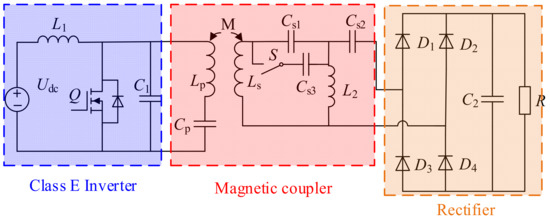
<p>The presented novel Class E topology.</p>
Full article ">Figure 2
<p>The working process waveform of inverter unit.</p>
Full article ">Figure 3
<p>T-type equivalent network.</p>
Full article ">Figure 4
<p>Equivalent circuit in CC mode. (<b>a</b>) Equivalent model. (<b>b</b>) Final equivalent model.</p>
Full article ">Figure 5
<p>Equivalent model in CV mode.</p>
Full article ">Figure 6
<p>(<b>a</b>) switching frequency <span class="html-italic">f</span> versus the coupling coefficient <span class="html-italic">k</span> when <span class="html-italic">α</span> changes; (<b>b</b>) switching frequency <span class="html-italic">f</span> versus the coupling coefficient <span class="html-italic">k</span> when <span class="html-italic">β</span> changes.</p>
Full article ">Figure 7
<p>The relationship between parameters <span class="html-italic">α</span>, <span class="html-italic">β,</span> and frequency <span class="html-italic">f</span>.</p>
Full article ">Figure 8
<p>The variation of output with <span class="html-italic">C</span><sub>s</sub>, <span class="html-italic">α,</span> and <span class="html-italic">L</span><sub>2</sub>. (<b>a</b>,<b>c</b>) CV mode; (<b>b</b>,<b>d</b>) CC mode of operation.</p>
Full article ">Figure 8 Cont.
<p>The variation of output with <span class="html-italic">C</span><sub>s</sub>, <span class="html-italic">α,</span> and <span class="html-italic">L</span><sub>2</sub>. (<b>a</b>,<b>c</b>) CV mode; (<b>b</b>,<b>d</b>) CC mode of operation.</p>
Full article ">Figure 9
<p>Wireless charging prototype using proposed topology.</p>
Full article ">Figure 10
<p>The <span class="html-italic">u</span><sub>ds</sub> and <span class="html-italic">u</span><sub>gs</sub> in CC and CV mode. (<b>a</b>) CC mode; (<b>b</b>) CV mode.</p>
Full article ">Figure 11
<p>Waveform of output voltage and current. (<b>a</b>) Load 20 Ω-10 Ω-20 Ω changes in CC mode; (<b>b</b>) load 20 Ω-40 Ω-20 Ω changes in CV mode.</p>
Full article ">Figure 12
<p>Dynamic performance of the system when the load is 20 Ω.</p>
Full article ">Figure 13
<p>Theoretical and measured values of output voltage and current.</p>
Full article ">Figure 14
<p>System efficiency graph.</p>
Full article ">
26 pages, 2902 KiB  
Review
A Review of Wireless Power Transfer Systems for Electric Vehicle Battery Charging with a Focus on Inductive Coupling
by Iman Okasili, Ahmad Elkhateb and Timothy Littler
Electronics 2022, 11(9), 1355; https://doi.org/10.3390/electronics11091355 - 24 Apr 2022
Cited by 42 | Viewed by 15648
Abstract
This article classifies, describes, and critically compares different compensation schemes, converter topologies, control methods, and coil structures of wireless power transfer systems for electric vehicle battery charging, focusing on inductive power transfer. It outlines a path from the conception of the technology to [...] Read more.
This article classifies, describes, and critically compares different compensation schemes, converter topologies, control methods, and coil structures of wireless power transfer systems for electric vehicle battery charging, focusing on inductive power transfer. It outlines a path from the conception of the technology to the modern and cutting edge of the technology. First, the base principles of inductive coupling power transfer are supplied to give an appreciation for the operation and design of the systems. Then, compensation topologies and soft-switching techniques are introduced. Reimagined converter layouts that deviate from the typical power electronics topologies are introduced. Control methods are detailed alongside topologies, and the generalities of control are also included. The paper then addresses other essential aspects of wireless power transfer systems such as coil design, infrastructure, cost, and safety standards to give a broader context for the technology. Discussions and recommendations are also provided. This paper aims to explain the technology, its modern advancements, and its importance. With the need for electrification mounting and the automotive industry being at the forefront of concern, recent advances in wireless power transfer will inevitably play an essential role in the coming years to propel electric vehicles into the common mode of choice. Full article
Show Figures

Figure 1

Figure 1
<p>Basic Inductive Power Transfer System with leakage inductance.</p>
Full article ">Figure 2
<p>Four basic compensation topologies: (<b>a</b>) SS, (<b>b</b>) SP, (<b>c</b>) PS and (<b>d</b>) PP.</p>
Full article ">Figure 3
<p>WPT converter topologies. (Where PFC is power factor correction).</p>
Full article ">Figure 4
<p>(<b>a</b>) Ćuk converter (<b>b</b>) P5 Converter.</p>
Full article ">Figure 5
<p>Bi-Directional Converter Topology.</p>
Full article ">Figure 6
<p>SS Compensated WPT System.</p>
Full article ">Figure 7
<p>Switch Controlled Capacitor.</p>
Full article ">Figure 8
<p>J1772 control pilot signal states.</p>
Full article ">Figure 9
<p>Coil Structures of WPT Systems for EV Battery Charging Including Ferrite Back-Plates. (<b>a</b>) Circular Coil. (<b>b</b>) Planar Square Coil. (<b>c</b>) DD Coil. (<b>d</b>) Bi-Polar Pad. (<b>e</b>) DDQ Coil. (<b>f</b>) Solenoid Coil.</p>
Full article ">Figure 10
<p>(<b>a</b>) I-Type and (<b>b</b>) W-Type Dynamic Track.</p>
Full article ">
25 pages, 9859 KiB  
Article
Structural Analysis of Loosely Coupled Transformers with FEA-Aided Visualization for Wireless Power Transfer Systems against Misalignment Tolerance
by Yao Zhang, Jiayang Li, Fan Zhang, Zhangping Chen, Yaguang Kong and Na Huang
Electronics 2022, 11(8), 1218; https://doi.org/10.3390/electronics11081218 - 12 Apr 2022
Cited by 2 | Viewed by 2196
Abstract
The main problems of automotive wireless power transmission (WPT) systems include a weak misalignment tolerance are urgently required to be solved through the design of the loosely coupled transformer. In this paper, an analysis methodology based on finite element analysis (FEA) visualization is [...] Read more.
The main problems of automotive wireless power transmission (WPT) systems include a weak misalignment tolerance are urgently required to be solved through the design of the loosely coupled transformer. In this paper, an analysis methodology based on finite element analysis (FEA) visualization is proposed, it is easy-implemented and straightforwardly explains this complex electromagnetic phenomenon. Firstly, the transformer structures with different winding and magnetic core arrangement were modeled by FEA in both 3-D and 2-D visualizations. The distribution of space coupling magnetic fields and leakage fields was analyzed by ANSYS Electronics. The key parameters that have a great influence on the coupling performance were delicately chosen. Then, the quantitative analysis of these key parameters and coupling performance against misalignment tolerance is presented. The numerical statistical result shows that the maximum coupling coefficient of the three structures that have been optimized consistently appears when the two key parameters, the inner and outer diameter, account for about 20% and 60% of the whole dimension of the transformers. A new transformer with a solenoid-shaped structure and strong misalignment tolerance was proposed based on the analysis methodology and the FEA results of the three structures. The delivered power and transfer efficiency under different misalignments of the new structure were analyzed via an FEA-aided joint method as well. The relationships among misalignment tolerance, key structural dimensions and coupling coefficients for all these structures were comprehensively investigated, which provide guidance for the subsequent multi-objective optimization strategies. Full article
Show Figures

Figure 1

Figure 1
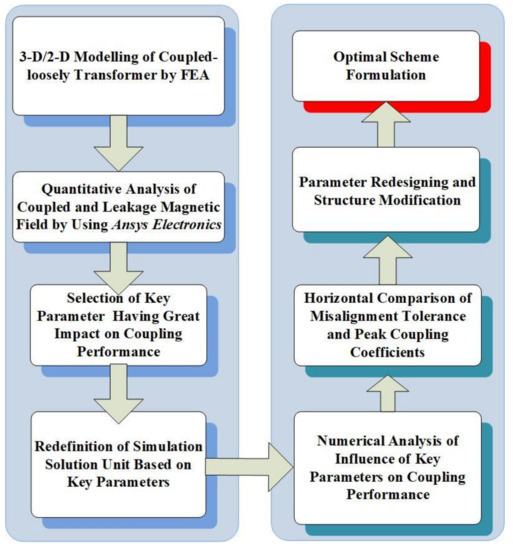
<p>FEA-aided methodology of a loosely coupled transformer.</p>
Full article ">Figure 2
<p>The 3-D visualization of the circular structure transformer.</p>
Full article ">Figure 3
<p>Dimensioning map of the circular structure in 2-D: (<b>a</b>) side view; (<b>b</b>) primary side.</p>
Full article ">Figure 4
<p>Spatially magnetic field distribution of the circular transformer with different inner and outer diameters: (<b>a</b>) nephogram of magnetic field intensity in coil with narrow inner diameter; (<b>b</b>) vector diagram of magnetic field intensity in coil with narrow inner diameter; (<b>c</b>) nephogram of magnetic field intensity in coil with wide inner diameter; (<b>d</b>) vector diagram of magnetic field intensity in coil with wide inner diameter; (<b>e</b>) nephogram of magnetic field intensity in coil with narrow outer diameter; (<b>f</b>) vector diagram of magnetic field intensity in coil with narrow outer diameter.</p>
Full article ">Figure 5
<p>The relationship among the inner and outer diameters of the coil and the coupling coefficient of the circular transformer.</p>
Full article ">Figure 6
<p>The relationship among horizontal, vertical misalignment, and the coupling coefficient of the circular transformer.</p>
Full article ">Figure 7
<p>Overall structure of the rectangular structure transformer in 3-D.</p>
Full article ">Figure 8
<p>Dimensioning diagram of the primary side of the rectangular structure transformer in 2-D.</p>
Full article ">Figure 9
<p>Relationship diagram among the inner and outer diameters of the coil and the coupling coefficient of rectangular structure transformer.</p>
Full article ">Figure 10
<p>Relationship diagram of the coupling coefficient and ferrite direction misalignment in a transformer with rectangular structure.</p>
Full article ">Figure 11
<p>Relationship diagram of the coupling coefficient and misalignment perpendicular to the ferrite direction in a transformer with rectangular structure.</p>
Full article ">Figure 12
<p>Schematic diagram of coupling magnetic field direction: (<b>a</b>) single-sided single-winding structure; (<b>b</b>) single-sided multi-winding structure.</p>
Full article ">Figure 13
<p>Overall map of the DD structure transformer in 3-D.</p>
Full article ">Figure 14
<p>Key geometrical parameters of the DD structure.</p>
Full article ">Figure 15
<p>The relationship diagram among the coupling coefficient and coil diameter and width under uniform distribution of ferrite in DD structure transformer.</p>
Full article ">Figure 16
<p>Relationship diagram between the horizontal misalignment and the coupling coefficient of a transformer with DD structure.</p>
Full article ">Figure 17
<p>Schematic diagram of winding decoupling.</p>
Full article ">Figure 18
<p>Schematic diagram of key geometric parameters of the solenoid-structure transformer.</p>
Full article ">Figure 19
<p>Key geometric parameters of the bipolar structure transformer.</p>
Full article ">Figure 20
<p>System architecture of the transformer in 3-D.</p>
Full article ">Figure 21
<p>Relationship curve between the coupling coefficient and the coil overlap length.</p>
Full article ">Figure 22
<p>Relationship between the coupling coefficient of the primary coil and primary coil width.</p>
Full article ">Figure 23
<p>Relationship among the coupling coefficient and vertical and horizontal misalignment.</p>
Full article ">Figure 24
<p>S-LCL AC equivalent circuit.</p>
Full article ">Figure 25
<p>Variation diagram of system power with vertical misalignment distances offset perpendicular to the placement direction of the magnetic core.</p>
Full article ">Figure 26
<p>Variation diagram of system power with a horizontal offset.</p>
Full article ">
16 pages, 6162 KiB  
Article
Using Overlapped Resonators in Wireless Power Transfer for Uniform Electromagnetic Field and Removing Blank Spots in Free Moving Applications
by Saeideh Pahlavan, Mostafa Shooshtari, Mohammadreza Maleki and Shahin Jafarabadi Ashtiani
Electronics 2022, 11(8), 1204; https://doi.org/10.3390/electronics11081204 - 10 Apr 2022
Cited by 13 | Viewed by 3139
Abstract
We propose an induction link based on overlapping arrays to eliminate blank spots on the electromagnetic field for moving object applications. We use two arrays of four aligned coils that have a 50% overlap between the two plates. This mechanism compensates for the [...] Read more.
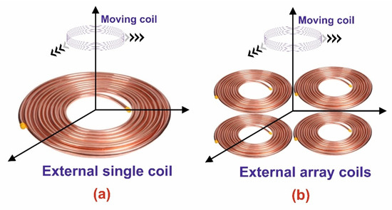
We propose an induction link based on overlapping arrays to eliminate blank spots on the electromagnetic field for moving object applications. We use two arrays of four aligned coils that have a 50% overlap between the two plates. This mechanism compensates for the internal coil power drop at positions in the boundaries between two adjacent external coils. We showed that if these plates are excited, a uniform electromagnetic field is created in the movement direction of the moving object. This uniform electromagnetic field distribution will result in a constant receiving power at all points in the path of the moving internal coil with the same power consumption of one coil excitation. Power delivery to the moving object tolerance reaches 10% at most, while, in non-overlapped scenarios, it is approximately 50%. In addition, according to the theoretical calculations, printed circuit coils (PCB) for the array are designed for maximum efficiency. We found that the change in distance and dimensions of the receiver coil has a linear effect on power and efficiency. Moreover, a Specific Absorption Rate (SAR) simulation was performed for biocompatibility. In this paper, we investigate and record a 68% electrical power efficiency for the fabricated system. The array consists of eight transmitters coils of the same size and shape and a receiver coil at a distance of 4 cm. Furthermore, the fabricated coil has shown improved efficiency compared to similar studies in the literature and introduces a promising structure for bio-test applications. Full article
Show Figures

Figure 1

Figure 1
<p>Schematic of inductive WPT system for (<b>a</b>) single external coil and (<b>b</b>) array external coil for free-moving object.</p>
Full article ">Figure 2
<p>(<b>a</b>) Schematic of inductive power transmission system. (<b>b</b>) Compact circuit model of a coil. (<b>c</b>) Coil size cross-section. (<b>d</b>) Multilayer model of PCB for parasitic elements.</p>
Full article ">Figure 3
<p>Impedance response of real and imaginary parts of Z<sub>11</sub> of the fabricated coil vs. frequency.</p>
Full article ">Figure 4
<p>(<b>a</b>) Fabricated coil arrays. (<b>b</b>) Schematic of one plate array coil vs. electromagnetic field distribution. (<b>c</b>) Schematic of two overlapped plate array coils vs. electromagnetic field distribution.</p>
Full article ">Figure 5
<p>(<b>a</b>) Schematic of Class D amplifier. (<b>b</b>) Circuit designed to run the LM2596 IC.</p>
Full article ">Figure 6
<p>(<b>a</b>) The proposed inductive WPT setup using the two overlapped external coils with PA and rectifier. (<b>b</b>) Fabricated PCB and PCB layout of transmitter board.</p>
Full article ">Figure 7
<p>(<b>a</b>) Voltage regulator and PA waveform. (<b>b</b>) Input and no-load output voltage of rectifier. (<b>c</b>) Input and output voltage to the 82 Ω load of rectifier (shown in the schematic of <a href="#electronics-11-01204-f006" class="html-fig">Figure 6</a>a).</p>
Full article ">Figure 8
<p>Electromagnetic field distribution and power transfer efficiency for (<b>a</b>) non-overlapped and (<b>b</b>) overlapped structures.</p>
Full article ">Figure 9
<p>Variation of delivered power to internal coil and system efficiency vs. height changes of internal coil (X position is fixed to 25 mm for all experimental).</p>
Full article ">Figure 10
<p>Electromagnetic field distribution over internal coil movement from (<b>a</b>) top of first external coil, (<b>b</b>) border of two neighborhood coils with a 50% overlapped coil, and (<b>c</b>) top of next neighboring external coil.</p>
Full article ">Figure 11
<p>3D SAR for human head at 13.56 MHz For internal coil excited by overlapped external coil array. (<b>a</b>) SAR side view. (<b>b</b>) SAR top view.</p>
Full article ">
23 pages, 10522 KiB  
Review
Research and Application of Capacitive Power Transfer System: A Review
by Zhulin Wang, Yiming Zhang, Xinghong He, Bo Luo and Ruikun Mai
Electronics 2022, 11(7), 1158; https://doi.org/10.3390/electronics11071158 - 6 Apr 2022
Cited by 27 | Viewed by 11076
Abstract
Capacitive power transfer (CPT) uses an electric field as the transfer medium to achieve wireless power transfer (WPT). Benefitting from the low eddy current loss, simple system structure and strong plasticity of the coupling coupler, the CPT system has recently gained much attention. [...] Read more.
Capacitive power transfer (CPT) uses an electric field as the transfer medium to achieve wireless power transfer (WPT). Benefitting from the low eddy current loss, simple system structure and strong plasticity of the coupling coupler, the CPT system has recently gained much attention. The CPT system has significantly improved transfer power, system efficiency, and transfer distance due to continuous research and discussion worldwide. This review briefly presents the basic working principle of the CPT system and summarizes the theoretical research in four aspects, including coupling coupler and high-frequency power converter. Following this, the review focuses on research in six key directions, including system modelling and efficiency optimization. The application of CPT technology in five fields, including medical devices and transportation, is also discussed. This review introduces the progress of CPT research in recent years, hoping to serve as a reference for researchers, to promote the further research and application of the CPT system. Full article
Show Figures

Figure 1

Figure 1
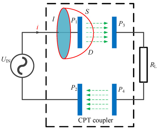
<p>General CPT circuit with a simplified coupling coupler.</p>
Full article ">Figure 2
<p>Structure diagram of CPT system.</p>
Full article ">Figure 3
<p>Coupler model by two capacitors connected in series.</p>
Full article ">Figure 4
<p>Different forms of CPT system coupler: (<b>a</b>) Parallel disc-shaped, annular coupling mechanism. Reprinted with permission from ref. [<a href="#B25-electronics-11-01158" class="html-bibr">25</a>], 2020 IEEE. (<b>b</b>) Parallel cylindrical coupling mechanism. Reprinted with permission from ref. [<a href="#B28-electronics-11-01158" class="html-bibr">28</a>]. (<b>c</b>) Laminated rectangular coupling mechanism. Reprinted with permission from ref. [<a href="#B29-electronics-11-01158" class="html-bibr">29</a>], 2019 IEEE. (<b>d</b>) Array type rectangular coupling mechanism. Reprinted with permission from ref. [<a href="#B30-electronics-11-01158" class="html-bibr">30</a>], 2019 IEEE.</p>
Full article ">Figure 5
<p>Equivalent circuit model for the typically four-plates coupler: (<b>a</b>) typical four-plate coupler, (<b>b</b>) full capacitor model, (<b>c</b>) π-model.</p>
Full article ">Figure 6
<p>Schematic diagram of single capacitor CPT system. Reprinted from ref. [<a href="#B85-electronics-11-01158" class="html-bibr">85</a>].</p>
Full article ">Figure 7
<p>System coupler with shielding plates and simulated electric field distribution. Reprinted with permission from ref. [<a href="#B22-electronics-11-01158" class="html-bibr">22</a>], 2018 IEEE: (<b>a</b>) coupler dimension; (<b>b</b>) simulated electric field distribution.</p>
Full article ">Figure 8
<p>Power supply for biomedical implants based on CPT system. Reprinted with permission from ref. [<a href="#B107-electronics-11-01158" class="html-bibr">107</a>], 2016 IEEE: (<b>a</b>) coupling model, (<b>b</b>) experiment.</p>
Full article ">Figure 9
<p>Schematic diagram of EV charging based on the CPT system by using concrete pavement and tire steel belt. Reprinted with permission from ref. [<a href="#B111-electronics-11-01158" class="html-bibr">111</a>], 2013 IEEE.</p>
Full article ">Figure 10
<p>Energy harvesting based on CPT system using power line insulators. Reprinted with permission from ref. [<a href="#B118-electronics-11-01158" class="html-bibr">118</a>], 2014 IEEE.</p>
Full article ">Figure 11
<p>Schematic diagram of system coupling coupler and underwater test. Reprinted from ref. [<a href="#B124-electronics-11-01158" class="html-bibr">124</a>].</p>
Full article ">Figure 12
<p>Pneumatic fluid bearing experimental device and circuit structure diagram. Reprinted with permission from ref. [<a href="#B126-electronics-11-01158" class="html-bibr">126</a>], 2014 IEEE.</p>
Full article ">
25 pages, 7603 KiB  
Article
A General Parameter Optimization Method for a Capacitive Power Transfer System with an Asymmetrical Structure
by Jinglin Xia, Xinmei Yuan, Sizhao Lu, Weiju Dai, Tong Li, Jun Li and Siqi Li
Electronics 2022, 11(6), 922; https://doi.org/10.3390/electronics11060922 - 16 Mar 2022
Cited by 5 | Viewed by 2123
Abstract
Capacitive power transfer (CPT) is an attractive wireless power transfer (WPT) technology and it has been widely studied in many applications. Symmetrical structures and high-order compensation networks are always produced as optimization results and common configurations for high-efficiency CPT systems. However, in space-limited [...] Read more.
Capacitive power transfer (CPT) is an attractive wireless power transfer (WPT) technology and it has been widely studied in many applications. Symmetrical structures and high-order compensation networks are always produced as optimization results and common configurations for high-efficiency CPT systems. However, in space-limited scenarios, an asymmetric structure tends to be a better choice. The related large number of high-order asymmetric system parameters is a key problem in parameter design. In this study, a general parameter design method that is based on reactive power optimization is proposed for an electric field resonance-based CPT system with an asymmetric six-plate coupler. The reactive power in the compensation network was analyzed and optimized under the constraint of transferred power. With equal reactive power, the optimization complexity was significantly reduced and the optimized system parameters were provided. To validate the effectiveness of the proposed method, a 1 MHz, 3.2 kW asymmetric CPT protype with 100 mm gap distance was implemented. The results indicate that, with the optimized parameters, high system efficiency can be achieved when the system’s volume is reduced. At the rated power, about 95% DC–DC overall efficiency was achieved through a 6-pF coupling capacitor. Full article
Show Figures

Figure 1

Figure 1
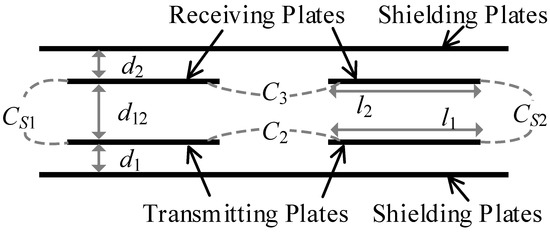
<p>Typical configuration of a capacitive coupler with six plates.</p>
Full article ">Figure 2
<p>Modelling of the capacitive coupler. (<b>a</b>) with four coupling capacitors. (<b>b</b>) with three coupling capacitors.</p>
Full article ">Figure 3
<p>Asymmetric structures of a six-plate coupler. (<b>a</b>) <span class="html-italic">l</span><sub>1</sub> = <span class="html-italic">l</span><sub>2</sub>, <span class="html-italic">d</span><sub>1</sub> &gt; <span class="html-italic">d</span><sub>2</sub>. (<b>b</b>) <span class="html-italic">l</span><sub>1</sub> &gt; <span class="html-italic">l</span><sub>2</sub>, <span class="html-italic">d</span><sub>1</sub> &gt; <span class="html-italic">d</span><sub>2</sub>. (<b>c</b>) <span class="html-italic">l</span><sub>1</sub> &lt; <span class="html-italic">l</span><sub>2</sub>, <span class="html-italic">d</span><sub>1</sub> &gt; <span class="html-italic">d</span><sub>2</sub>.</p>
Full article ">Figure 4
<p>An EFR-based asymmetric CPT system model.</p>
Full article ">Figure 5
<p>Equivalent circuit model of an asymmetric CPT system.</p>
Full article ">Figure 6
<p>Parameter design flowchart.</p>
Full article ">Figure 7
<p>Structure and dimensions of the asymmetric six-plate coupler.</p>
Full article ">Figure 8
<p>Optimization objective values under different plate length <span class="html-italic">l</span><sub>1</sub> and airgap distance <span class="html-italic">d</span><sub>1</sub>.</p>
Full article ">Figure 9
<p>Simulated capacitance and coefficients a and b under different airgap distance <span class="html-italic">d</span><sub>1</sub>. (<b>a</b>) Capacitance <span class="html-italic">C</span><sub>2</sub>, <span class="html-italic">C</span><sub>3</sub>, and <span class="html-italic">C<sub>S</sub></span>. (<b>b</b>) Coefficients <span class="html-italic">a</span> and <span class="html-italic">b</span>.</p>
Full article ">Figure 10
<p>Ratio of reactive power <span class="html-italic">Q</span> to transferred power under different airgap distance <span class="html-italic">d</span><sub>1</sub>.</p>
Full article ">Figure 11
<p>Values of <span class="html-italic">Q<sub>L</sub>/P</span> under different coefficient <span class="html-italic">a</span>.</p>
Full article ">Figure 12
<p>Simulated capacitances under X and Y misalignment conditions. (<b>a</b>) Misalignment along <span class="html-italic">x</span>-axis. (<b>b</b>) Misalignment along <span class="html-italic">y</span>-axis.</p>
Full article ">Figure 13
<p>Circuit model of actual inductor. (<b>a</b>) Equivalent circuit. (<b>b</b>) Simplified circuit.</p>
Full article ">Figure 14
<p>Simulation of <b>U</b><span class="html-italic"><sub>C</sub></span><sub>2</sub>, <b>U</b><span class="html-italic"><sub>C</sub></span><sub>3</sub>, <b>U</b><span class="html-italic"><sub>AB</sub></span>, and <b>I</b><sub>1</sub>.</p>
Full article ">Figure 15
<p>The simulated <span class="html-italic">Q</span> and <span class="html-italic">Q</span>/<span class="html-italic">P</span> at different output power <span class="html-italic">P<sub>out</sub></span>.</p>
Full article ">Figure 16
<p>System efficiency at different output power.</p>
Full article ">Figure 17
<p>Configuration of a 3.2-kW CPT prototype.</p>
Full article ">Figure 18
<p>Experimental Results. (<b>a</b>) Experimental <b>U</b><span class="html-italic"><sub>AB</sub></span> and <b>I</b><sub>1</sub>. (<b>b</b>) ZVS condition. (<b>c</b>) System efficiency.</p>
Full article ">Figure 19
<p>Experimental DC–DC efficiency at different output power.</p>
Full article ">Figure 20
<p>The estimated power loss distribution.</p>
Full article ">

2021

Jump to: 2023, 2022

17 pages, 6463 KiB  
Article
Collaborative Optimization Method of Power and Efficiency for LCC-S Wireless Power Transmission System
by Ming Xue, Qingxin Yang, Chunzhi Li, Pengcheng Zhang, Shuting Ma and Xin Zhang
Electronics 2021, 10(24), 3088; https://doi.org/10.3390/electronics10243088 - 12 Dec 2021
Cited by 4 | Viewed by 2290
Abstract
Dynamic wireless charging enables moving equipment such as electric vehicles, robots to be charged in motion, and thus is a research hotspot. The applications in practice, however, suffer from mutual inductance fluctuation due to unavoidable environmental disturbances. In addition, the load also changes [...] Read more.
Dynamic wireless charging enables moving equipment such as electric vehicles, robots to be charged in motion, and thus is a research hotspot. The applications in practice, however, suffer from mutual inductance fluctuation due to unavoidable environmental disturbances. In addition, the load also changes during operation, which makes the problem more complicated. This paper analyzes the impacts of equivalent load and mutual inductances variation over the system by LCC-S topology modeling utilizing two-port theory. The optimal load expression is derived. Moreover, a double-sided control strategy enabling optimal efficiency and power adjustment is proposed. Voltage conducting angles on the inverter and rectifier are introduced. The simulation and experimental results verify the proposed method. Full article
Show Figures

Figure 1

Figure 1
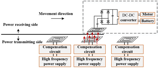
<p>Schematic diagram of the segmented rail type dynamic wireless power supply system.</p>
Full article ">Figure 2
<p>LCC-S type compensation topology equivalent circuit diagram.</p>
Full article ">Figure 3
<p>LCC-S type primary side equivalent circuit.</p>
Full article ">Figure 4
<p>The relationship between <span class="html-italic">R</span><sub>Leq</sub>, <span class="html-italic">M</span>, and <span class="html-italic">P</span><sub>o</sub>, <span class="html-italic">η</span>. (<b>a</b>) The relationship between <span class="html-italic">R</span><sub>Leq</sub>, <span class="html-italic">M</span>, and <span class="html-italic">P</span><sub>o</sub> and (<b>b</b>) the relationship between <span class="html-italic">R</span><sub>Leq</sub>, <span class="html-italic">M</span>, and <span class="html-italic">η</span>.</p>
Full article ">Figure 5
<p>WPT system based on half-controlled rectifier bridge.</p>
Full article ">Figure 6
<p>System control signal waveform values.</p>
Full article ">Figure 7
<p>The relationship between <span class="html-italic">η</span>, <span class="html-italic">R</span><sub>L</sub>, and rectifier bridge conduction angle <span class="html-italic">β</span>.</p>
Full article ">Figure 8
<p>Control system block diagram.</p>
Full article ">Figure 9
<p>Control flow chart.</p>
Full article ">Figure 10
<p>Change in mutual inductance during lateral shift.</p>
Full article ">Figure 11
<p>Changes in <span class="html-italic">P</span><sub>o</sub> and <span class="html-italic">η</span> under lateral offset. (<b>a</b>) Changes in output power <span class="html-italic">P</span><sub>o</sub> under lateral offset and (<b>b</b>) changes in transmission efficiency <span class="html-italic">η</span> under lateral offset.</p>
Full article ">Figure 12
<p>The relationship between <span class="html-italic">α</span>, <span class="html-italic">β</span>, and <span class="html-italic">M</span>.</p>
Full article ">Figure 13
<p>Changes in power and efficiency of different mutual inductances. (<b>a</b>) change in power under different mutual inductance and (<b>b</b>) change in efficiency under different mutual inductance.</p>
Full article ">Figure 14
<p>Change waveform of <span class="html-italic">U</span><sub>o</sub> when control is applied and when control is not applied. (<b>a</b>) Variable waveform of <span class="html-italic">U</span><sub>o</sub> under control and (<b>b</b>) waveforms of <span class="html-italic">U</span><sub>o</sub> change when non-control is applied.</p>
Full article ">Figure 15
<p>Changes in <span class="html-italic">P</span><sub>o</sub> and <span class="html-italic">η</span> under different <span class="html-italic">M</span> and <span class="html-italic">R</span><sub>L</sub>. (<b>a</b>) Changes in output power <span class="html-italic">P</span><sub>o</sub> under different <span class="html-italic">M</span> and <span class="html-italic">R</span><sub>L</sub> and (<b>b</b>) changes in efficiency <span class="html-italic">η</span> under different <span class="html-italic">M</span> and <span class="html-italic">R</span><sub>L</sub>.</p>
Full article ">Figure 16
<p>Experiment platform.</p>
Full article ">Figure 17
<p>Changes in output power and system efficiency at different offsets. (<b>a</b>) Changes in output power at different offsets and (<b>b</b>) changes in system efficiency at different offsets.</p>
Full article ">
Back to TopTop