Introduction
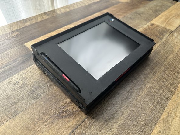
A complete teardown guide for the IBM ThinkPad 360P and 360PE "tablet" models. As with any old machine, expect the plastics to be brittle and break easily.
- Don't over-tighten screws
- Watch where you're bracing or resting your hands and arms
- Use the right size bits to prevent from stripping screws
- Clean as you go! DeoxIT is your friend.
What you need
-
-
Open the laptop bay by pulling back fully on the latches on both sides of the laptop until the front of the keyboard pops open.
-
Remove the battery by pulling up on the blue tab, lifting the end closest to the back up and out.
-
Remove the Hard Disk and Floppy Disk Drive by pulling the blue tabs towards you until the metal handle is dislodged, then use the handle to lift straight up, disconnecting them from the connectors below.
-
-
-
Gently close the keyboard (without locking it)
-
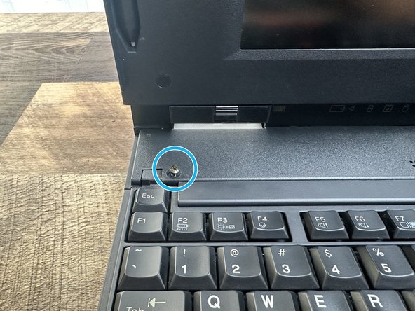
Remove the two (2) plastic screw covers from the keyboard cover using a thin tool. If you use a hobby knife or a blade, be sure not to cut or damage the screw covers.
-
Remove the two (2) M2.5x8mm screws from underneath the covers with a Philips head driver.
-
-
-
Open the keyboard fully and locate two clips holding the rear keyboard cover on. They will be located at the pivot point.
-
Use a pair of tweezers to release the clips on both sides by pulling towards you.
-
-
-
Close the keyboard (without latching it)
-
Push forward on the center of the keyboard cover to release the final clip. Once loose, pull towards you and set aside.
-
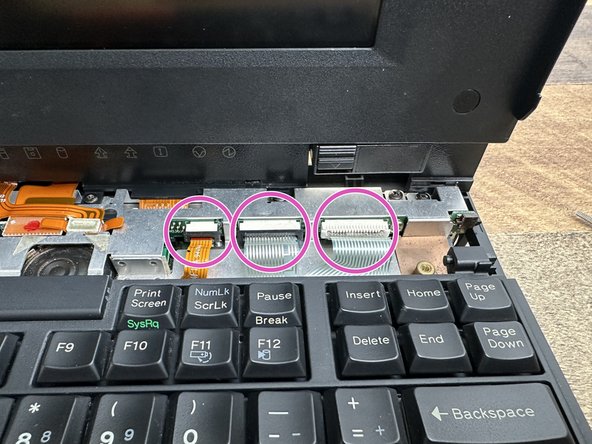
Remove the three (3) keyboard ribbon cables by unclipping them from the connectors. Do this by using a plastic spudger or pair of tweezers by pulling each side of the clip towards you. Once loosened you can pull the ribbon cable out.
-
You can now remove the keyboard and set it aside.
-
-
-
If a RAM card is in the slot, remove it by slightly levering up to clear the plastic holder and pull towards you.
-
Remove the single (1) M2.5x5mm screw from the battery cover using a Philips head driver.
-
You should now be able to remove the plastic RAM holder.
-
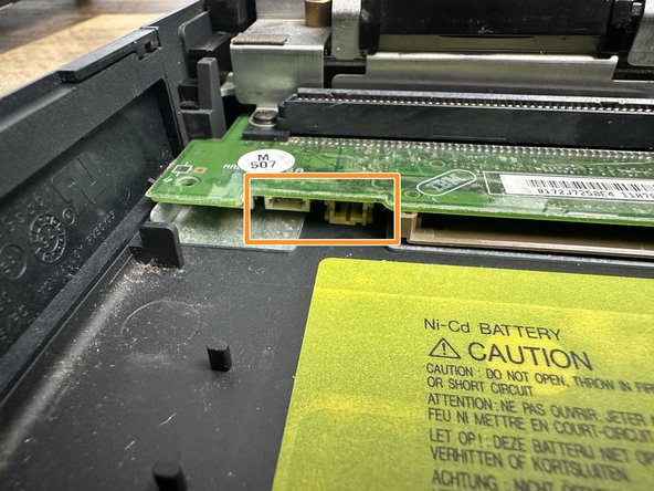
There may be one (1) or two (2) batteries plugged on the underside of the board. Disconnect and remove them before continuing.
-
Remove the diskette drive bezel by pulling up and out of the case.
-
-
-
-
Open the display so that it lays all the way back.
-
Remove the two (2) M2.5x5mm screws as shown using a Philips head driver.
-
Disconnect the ribbon cable from the connector using tweezers or a plastic spudger. Do NOT pull directly on the cable.
-
Press in on both sides of the Status Indicator to dislodge the clips from under the shielding.
-
You should now be able to remove the status indicator and set aside.
-
-
-
Remove the two (2) highlighted connectors first. You can use the tabs connected to the ribbon cables, but do NOT pull on the cables themselves. Each cable has a hard plastic stiffener attached that can be used to lever the cables out if the tabs are damaged or missing.
-
Remove the second set of cables AND the single (1) M2.5x5mm Philips screw that connects one of the cables to the shield.
-
Using a pair of tweezers or plastic spudger, release the clip on the back to remove the hinge covers on both sides.
-
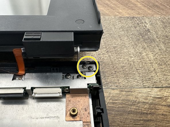
Remove the two (2) M2.5x4mm screws connecting the display to the case on both sides.
-
The display assembly should now be able to be removed and set aside.
-
-
-
Remove the black clip connecting the shields (if present).
-
Remove the single (1) M2.5x4mm Philips screw from the top as shown.
-
Remove the two (2) M2.5x8mm Philips screws securing the shield to the Floppy Disk Drive connector.
-
You should now be able to lift the left Audio Card shield up and out. Set aside.
-
-
-
First, use a plastic pick to remove the plastic battery shield being careful not to tear the plastic.
-
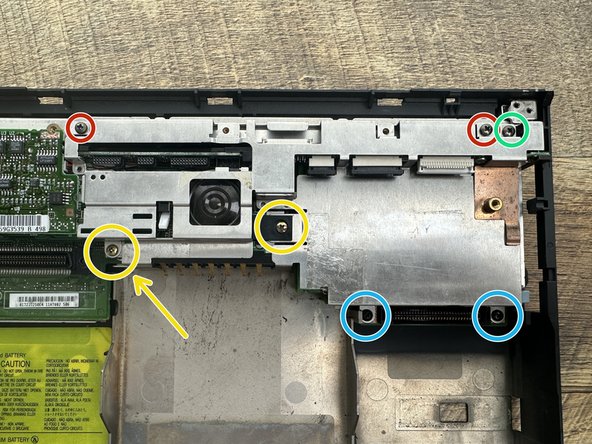
Remove the two (2) M2.5x4mm Philips screws from the top where indicated.
-
Remove the single (1) M2.5x3mm Philips screw where indicated.
-
Remove the two (2) M2.5x16mm Philips screws from the bottom left by the battery. When removing the left screw (indicated by the arrow) make sure to save the plastic spacer underneath.
-
Remove the two (2) M2.5x6mm Philips screws from the bottom right securing the HDD connector.
-
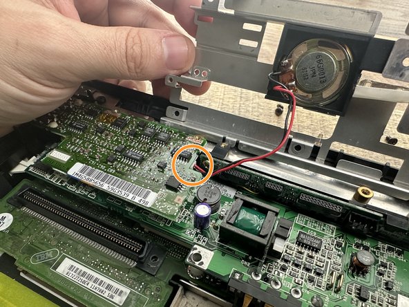
Disconnect the speaker cable from the Audio Board. You can then remove the Main Shield and set aside.
-
-
-
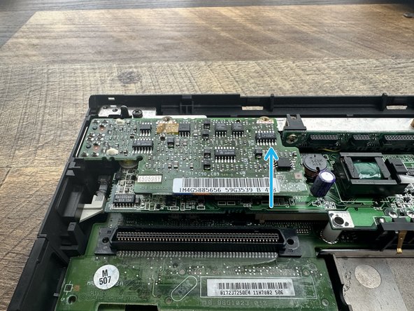
Lifting from the right, pull the Interposer Board up and away from the connector on the left. Set aside.
-
-
-
Remove the Audio Board from the connector by lifting it up from the right, then pulling straight up and out.
-
Remove the top single (1) M2.5x4mm Philips screw from the top along with the metal bracer.
-
Remove the single (1) M2.5x7mm countersunk Philips screw from the power jack.
-
Remove the Power Board from the connector by lifting up from the right, then pulling straight up and out.
-
-
-
Remove the two (2) M2.5x4mm Philips screws from each side of the rear of the case.
-
Lift the screw brackets up and away from the case.
-
-
-
From the back of the case, remove the two (2) 5.5mm hex bolts from either side of the dock connector.
-
Remove the six (6) 5mm hex bolts from either side of the serial, parallel and display connetors.
-
To remove the main board, carefuly lift up the back and move towards the front of the case. There are two areas, one on each side that you'll need to be careful to clear.
-
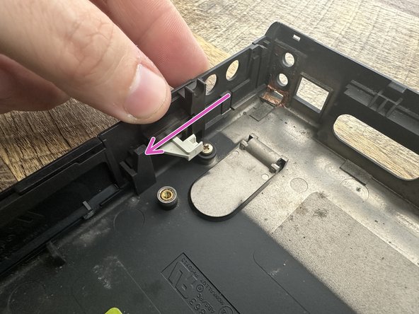
Reassembly Tip: Make sure the power slide is all the way toward the case when reassembling. The switch on the main board should rest in the notch inside the white arm of the slide.
-
-
-
Remove the Pen (if present).
-
Remove the three (3) plastic screw covers using a hobby knife. Insert the blade so its just underneath the cover, then use the back of the knife to remove to prevent cutting the cover. Then, remove the three (3) M2x8mm Philips screws.
-
Remove the single (1) plastic screw cover as detailed above. Then remove the single (1) M2x5mm Philips screw.
-
Remove the IBM ThinkPad decal using a similar technique to the screw covers, revealing a single (1) M2x8mm Philips screw. Remove to continue.
-
To loosen the bezel, insert a plastic pick underneath the left display latch at the top of the pen slot. Then, using a second pick, begin dislodging the clips along the top of the bezel until it pops off.
-
Tilt the bezel towards you, being careful not to stress the clips securing the bottom, and remove.
-
-
-
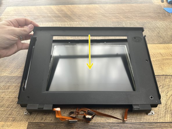
Disconnect the power cable to the LCD from the inverter board.
-
Remove the single (1) M2x7mm Philips head screw and washer where indicated.
-
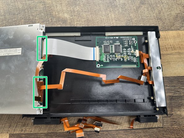
Fold out the LCD panel being careful not to damage the two (2) ribbon cables connected on the underside of the left side of the panel.
-
Disconnect the two (2) ribbon cables from the rear of the LCD panel. Remove and set aside.
-
To reassemble your device, follow these instructions in reverse order.
To reassemble your device, follow these instructions in reverse order.
Cancel: I did not complete this guide.
One other person completed this guide.
