Imagine you have been made many power amplifiers. Because you love to listen to music.
You like lighting with music, right? An LM3914 VU Meter circuit is a great IC that should know.
How?
This IC can drive LED displays to show the power audio level, so beautiful.
Many friends also love they are the same as me.
Why use it?

Popular—When you go to the electronic components store to buy the VU meter kit. To assemble various parts or styles ready to use. You will see LM3914 a lot.
Easy to modify —in any form. For example, Flashing lights to decorate the Christmas tree, exotic, and unique. Someone uses it to make Voltmeter in 10 level display.
Cheap—Good value for your money and time.
Are you interested in it?
Look:
OR continue to read below!
LM3914 Datasheet
Before we use it. We should have a rough understanding of its characteristics first for smooth operation.
The simple Features
Here is Features of LM3914
- Drives LEDs, LCDs or vacuum fluorescents
- Bar or dot display mode externally selectable by user
- Expandable to displays of 100 steps
- Internal voltage reference from 1.2V to 12V
- Operates with single supply of less than 3V
- Inputs operate down to ground
- Output current programmable from 2 mA to 30 mA
- No multiplex switching or interaction between outputs
- Input withstands 35V without damage or false outputs
- LED driver outputs are current regulated, open-collectors
- Outputs can interface with TTL or CMOS logic
- The internal 10-step divider is floating and can be referenced to a wide range of voltages
LM3914 pinout
In most cases, we’ll see it in the Dual-in-Line Package 18 pin.
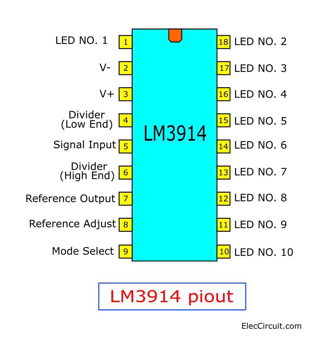
They have 3 siblings, LM3914, LM3915, and LM3916. The shape is the same. But the main difference is that the LM3914 displays a linear scale.
LM3915 displays Log scale and LM3916 displays in Semi Log scale. Which we will learn in the next opportunity.
Basic LM3914 Block Diagram
See the Internal structure and basic external devices of the LM3914.
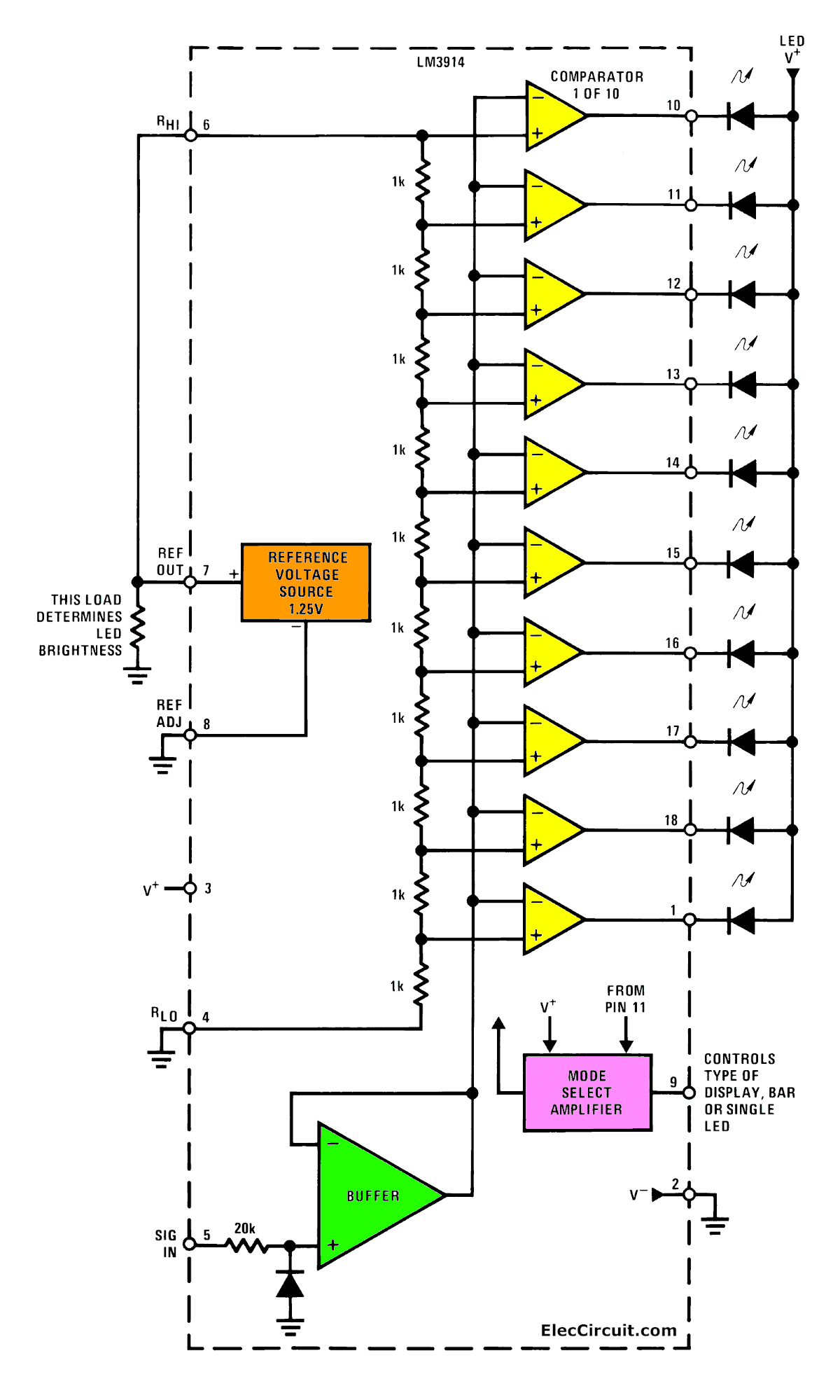
We enter the voltage to be measured to pin 5 (withstand voltage up to + 35V). And, through the buffer, which has a gain of one. Then, come to the inverting input of 10 op-amps. The output of each op-amp can drive the current up to 30mA.
LED brightness Control
The current flowing through each LED can be controlled at R1 which is connected between pin 7 and pin 8. And at pin 7 give a reference voltage of 1.2V. When compared to pin 8, R1 is equal to 1.2K. It results in the current flowing from pin 7 approximately equal to 1mA.
When compared to pin 8, R1 is equal to 1.2K. It results in the current flowing from pin 7 approximately equal to 1mA. So, the current flowing in each LED is about 10mA or about 10 times the current on pin 7.
LM3914 Display MODE
See pin 9 is used to control the Mode of the LED display. If left floating, this pin will display in Dot mode. If connected to pin 3 it will display as Bar Graph.
Do you imagine?
- Bar graph mode — connected pin 9 to pin 3. For example, if the input voltage is 0.36V, LED1, LED2, and LED3 will light.
(LED1 starts to bright as 0.12V, LED2 lights at 0.24V, LED3 at 0.36V) - Dot mode — leave pin 9 floating. In this case, if the input voltage is 0.36V, the result is only LED3 is bright.
LM3915 & LM3916
In the case of the LM3915, the series resistance within the IC will not all be equal. They are arranged in a Log Scale Mode. This will produce a difference of 3 dB in each step. For example, the 10th step would be 30 dB.
In the case of the LM3916, the internal resistance values are arranged in a Semi log scale. An example of using the LM3916 is a VU meter.
Example LM3914 circuit
Not only that we will learn how to use it with the example circuit below.
1.2V to 1000V Voltmeter circuit using LM3914
See the circuit below. It is an example of a dot display.
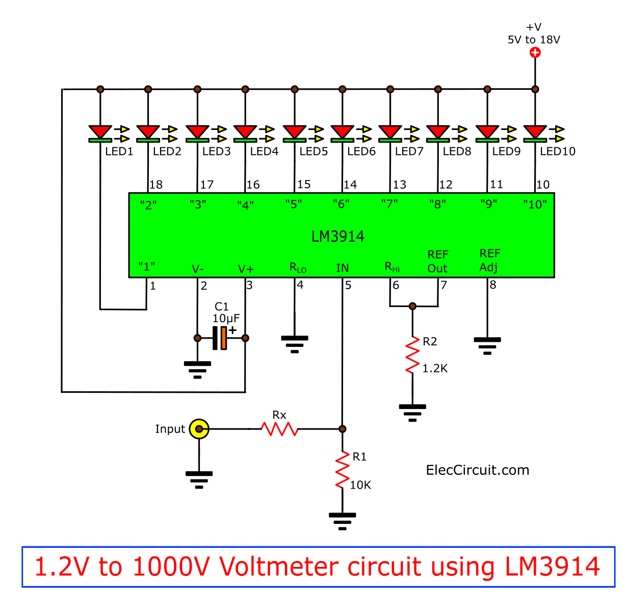
It can display measurement results at full scale from 1.2V to 1000V depending on the configuration of Rx. For example, if Rx = 0 ohms will give full-scale reading equal to 1.2V.
0-10V Voltmeter circuit using Zener and LM3914
See the circuit below, pin 4 connects to the ground and pin 6 with 10V Zener diode.
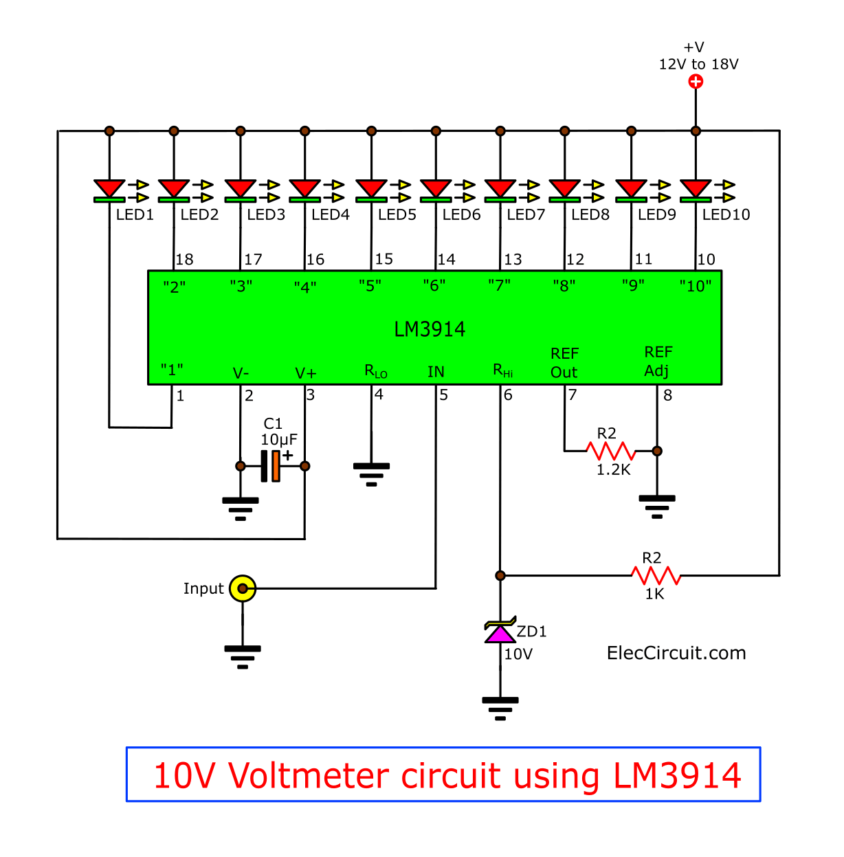
It results in a display in the range of 0-10V, with each stage of illumination between the neighboring LEDs equal to 1V.
Voltmeter with full-scale voltage adjustable
What is more? See the circuit below.
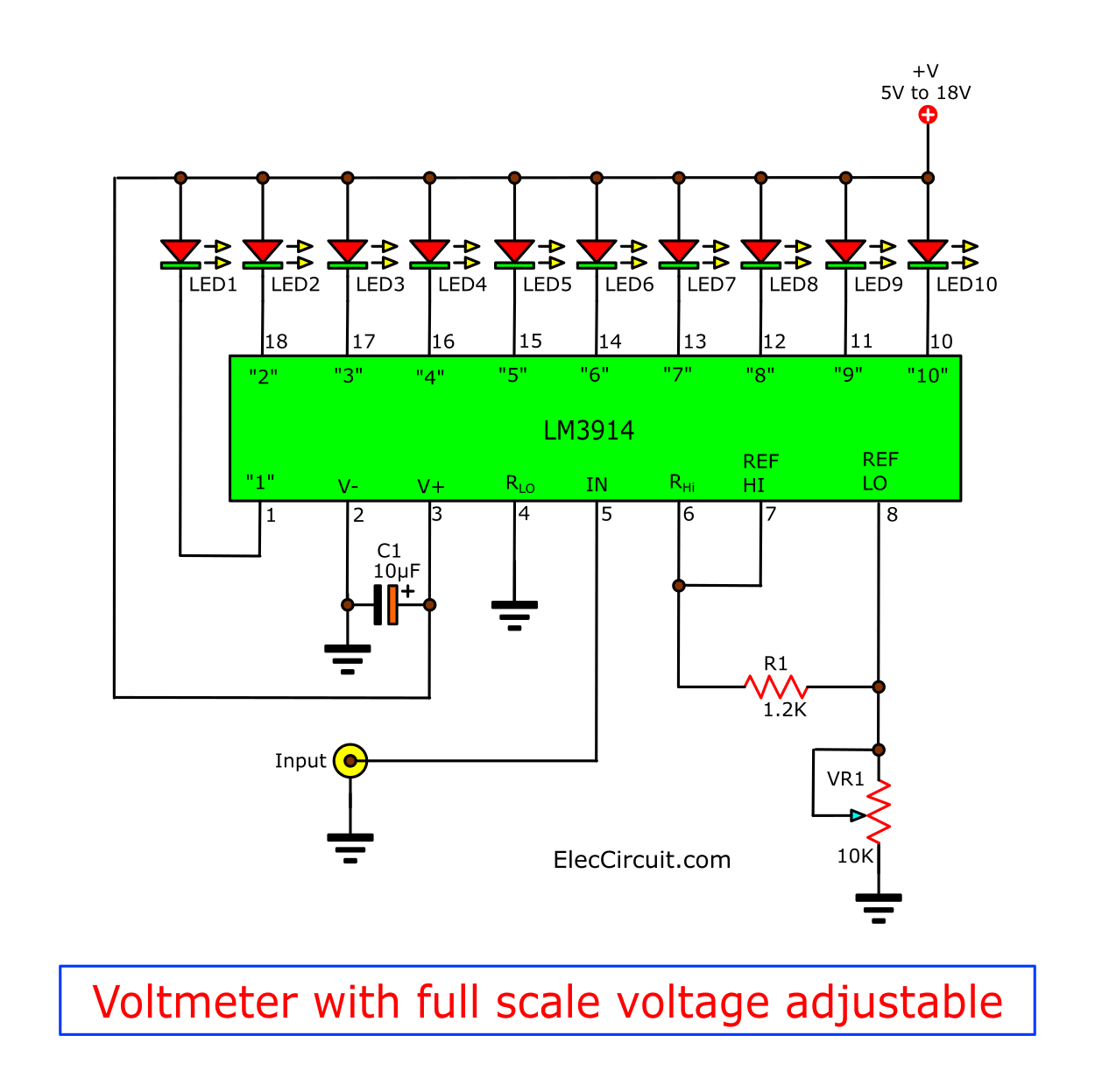
It will allow full-scale voltage adjustment by adjusting VR1. For example, Adjusting VR1 to 2.4K will cause the voltage at pin 8 to rise to 2.4V. As a result, the voltage at pin 7 goes up to 3.6V. So we can read it full-scale now equal to 3.6V.
And, if VR1 is adjusted to a value of 9.8K. It will give a full-scale reading of 11V.
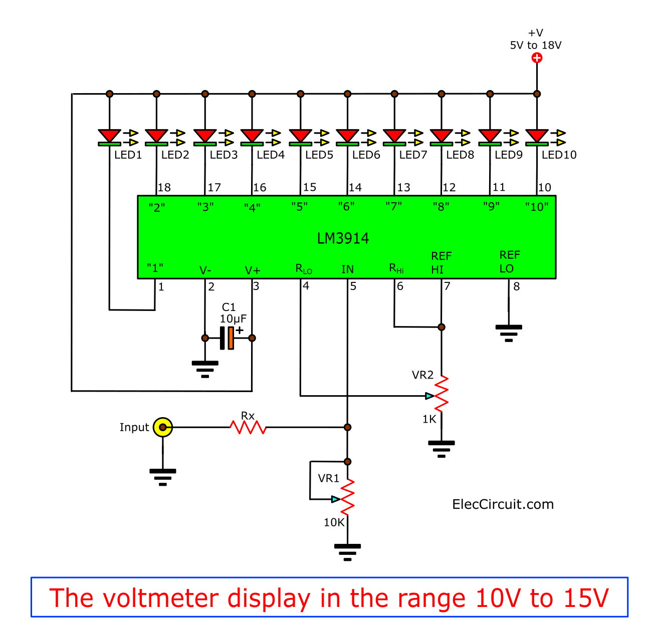
The voltmeter display in the range 10V to 15V
See the circuit
The full-scale voltmeter alarm circuit
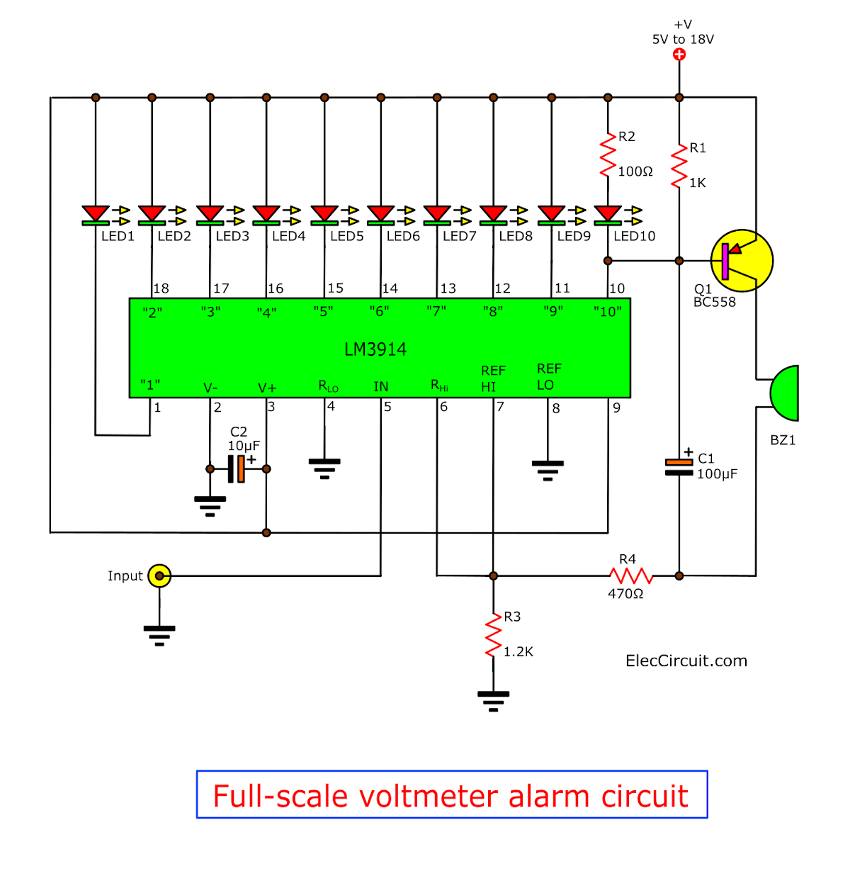
This will shout. When a full-scale measurement occurs. This is a result of the low voltage pin 10 of IC1. As a result, the transistor-Q1 works, and the buzzer sounds.
Want more brilliant ideas? Here’s how to get them through electronic circuits.
VU meter circuit Stereo/Mono 20 LED with PCB
Here are LM3914/LM3915 VU meter circuit projects. They can display with 20 LEDs on stereo or mono with 10 LEDs for all audio systems.
Also, we can easily build and cheap. We will be happy when using them. Read More…
See the circuit below.
This will shout. When a full-scale measurement occurs. This is a result of the low voltage pin 10 of IC1. As a result, the transistor-Q1 works, and the buzzer sounds.
LED Light-Based Music circuit using LM3914
Let’s build a simple running light with music. This is not a hard circuit. In MONO form with a few components. We can connect it to the output of a CD or cassette player or low signal source.
Operation of the circuit
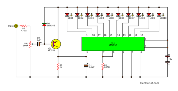
To begin with the input signal via VR1. The VR1 will function to adjust the level of this input signal.
Then, D1 will block a positive signal away, leaving only the negative signal to be the bias of Q1.
Next, Q1(PNP transistor) will increase up signal more to pin 5 (input) of IC1.
After that C1 is a time delay of the out’s IC1 to keep LED does not turn off immediately. This act shows the effect of the voltage at IC1 pin 5 on the LED display within range output pins 1-19.
Inside IC has a voltage comparator section for comparing to multiple voltages of standard circuits. So, this can operate effectively.
In case we want to connect the input of the circuit to the speaker terminals. We should change the value of R3 is 10K.
And we can choose to display 2 Mode. First, Bar Mode, connect pin 9 to a positive voltage source. Second, Dots Mode lave pin 9 floating.
60 LED Music Lighting Stereo VU meter with multi-system
This circuit is another name for the VU meter. which often have a lot of equipment. Cause problems for people who start training. But this cycle is not much equipment. You can also choose, in the.
Running a bar or run with a point.
Operation of the circuit
It is the primary device IC number LM3914N is ready to show the effects of pressure, like a bar or have a point.
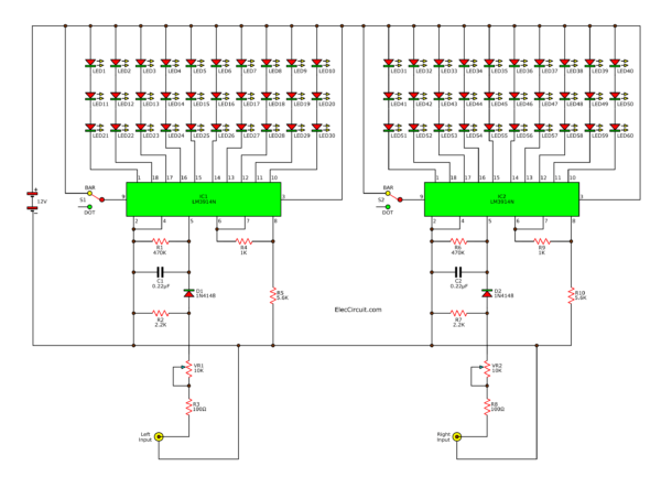
The behavior of IC1 and IC2 is similar circuit R2, R3, VR1 is connected in the manner divided voltage to the input to the voltage appropriate, through D1 to Pin 5.
Which R1 and C1 are waiting for a delay. Input pin 5 not to fade away soon.
When a signal to the output of each IC pin is connected to the 3-Series LED, to limit the flow.
But if you want the LED on the moon alone would have to go with the R series.
The S1, S2 are an optional format of the display LED.
Read: LM3914 Datasheet
Hey friend! you may like these circuits, too. See!
GET UPDATE VIA EMAIL
I always try to make Electronics Learning Easy.
Related Posts
I love electronics. I have been learning about them through creating simple electronic circuits or small projects. And now I am also having my children do the same. Nevertheless, I hope you found the experiences we shared on this site useful and fulfilling.


thank you!!
Hi all, can any one tell me that how to connect multiple ic 3915 more than two. Please help. Thanks in advance!
Hi satheesh G,
Please look at : https://www.eleccircuit.com/electronic-vu-meter-by-lm3914-and-lm3915/
hi friends, i find dot,bar and peak hold function led levelmeter circuits.using ics cd4066,lm3915,15,16 and ne 555. i found many videos on youtube. but not found circuits any electronics site. pls help
https://www.youtube.com/watch?v=8mAkWvulAno
I really like your vu circuit. Thank you for sharing this!
I analyzed the bias circuit on the transistor
amplifier. This is a neat design! The formula for
the emitter.current came out to be:
IE = ( Vcc – Vbe) / (R1 / beta+ R2 + R3)
This can be used to find the small signal voltage gain:
Voltage gain = gm * total load resistance
gm = (alpha * IE / 26 mV)
Then :
V out / Vin = gm * total load resistance
and
voltage gain = V out / V in
thus ; V out = gm * total load resistance * V in
I hope this helps anyone.
Awesome thanks heaps dude.
This is killa for music lovers!!!
What about a circuit to run 500mm of 12v led RGB strips for each frequency not thats KILLA!!!