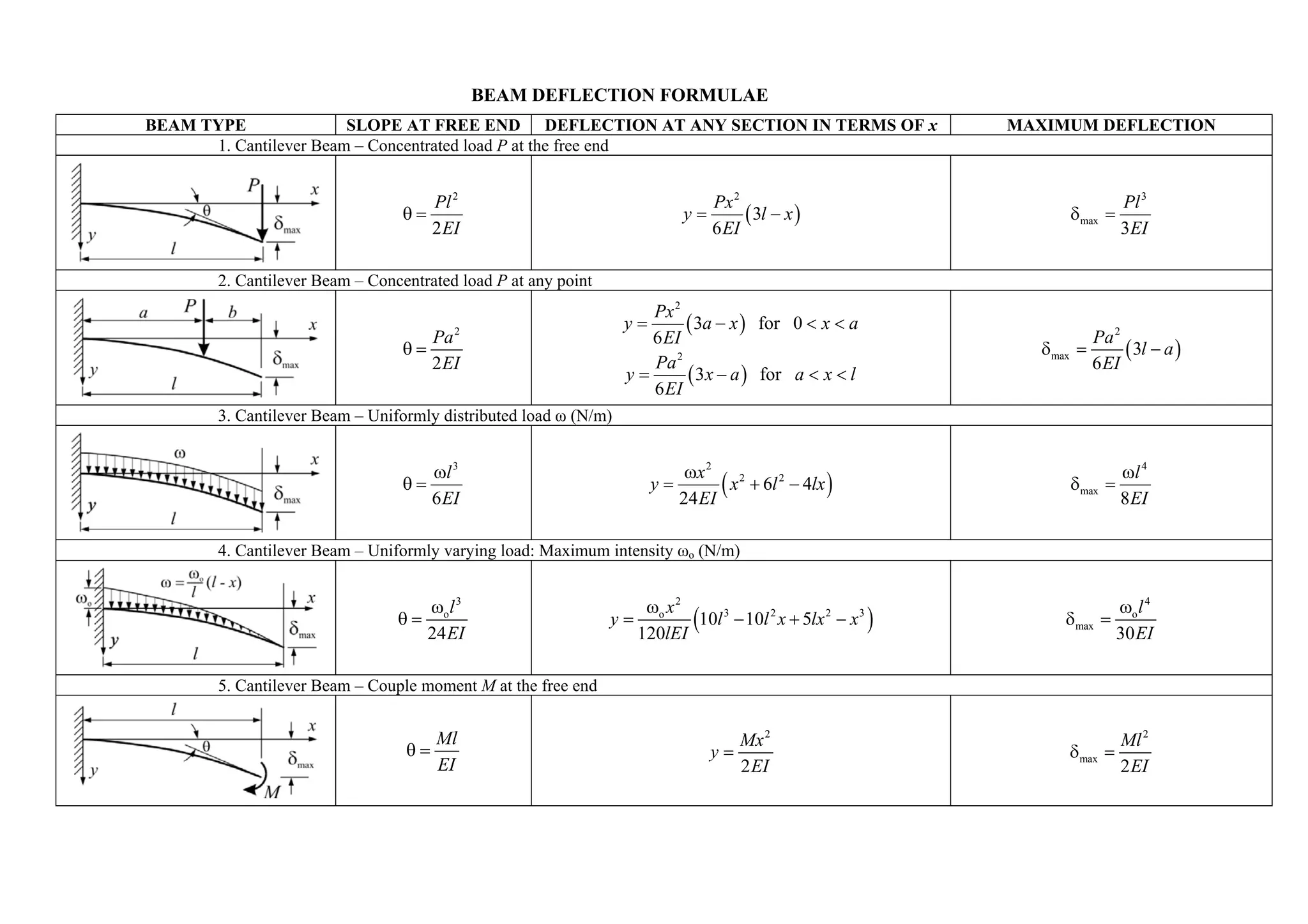
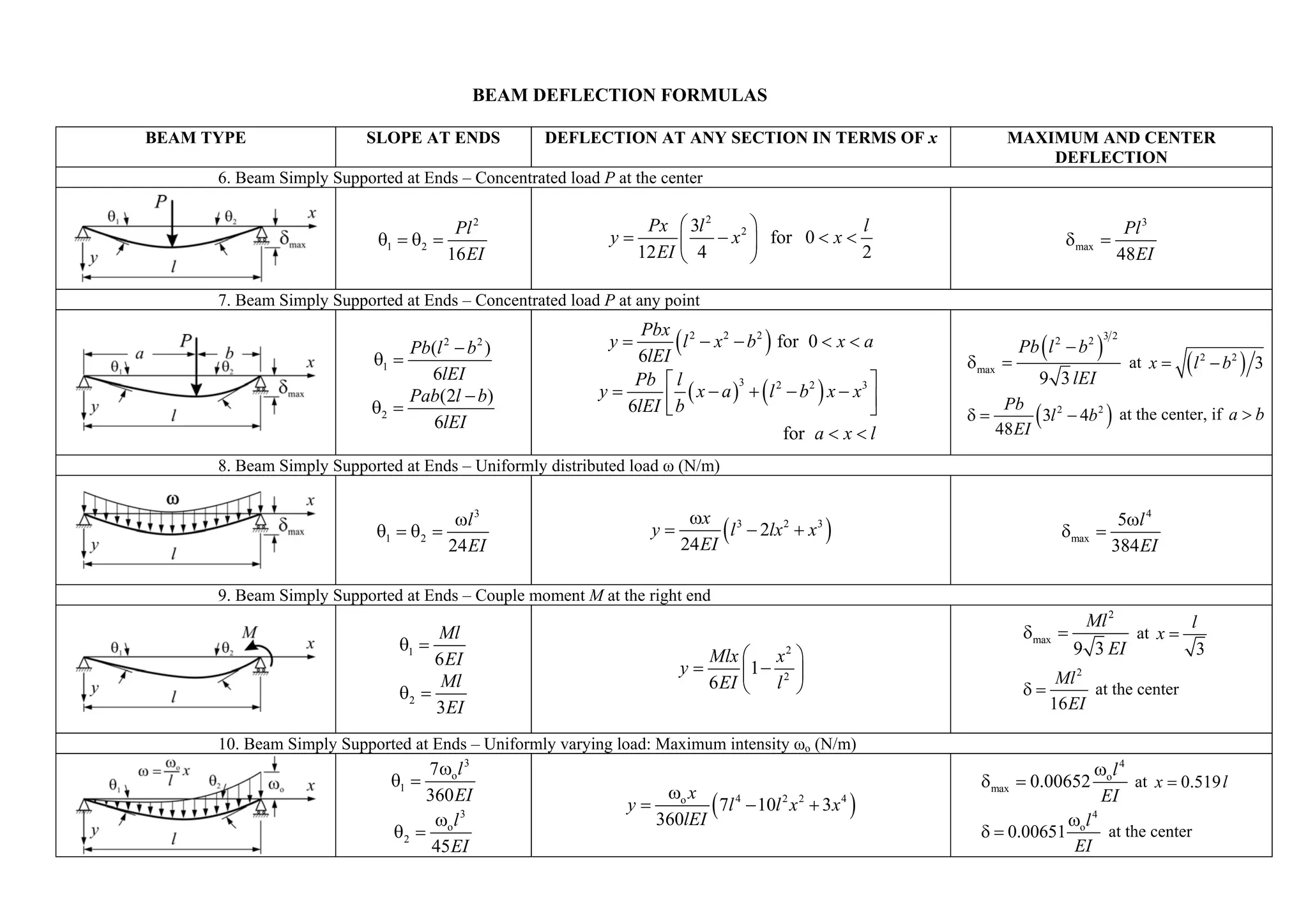
1. The document provides formulas for calculating slope, deflection, and maximum deflection for various beam types under different loading conditions. It gives the equations for cantilever beams with concentrated loads, uniformly distributed loads, and varying loads. It also provides the equations for simply supported beams with these different load types and with couple moments applied. The equations relate the beam properties like length, load location, and intensity to the resulting slope and deflection values.
The document discusses bending stresses in beams. It describes how bending stresses are developed in beams to resist bending moments and shearing forces. The theory of pure bending is introduced, where only bending stresses are considered without the effect of shear. Equations for calculating bending stresses are derived based on the beam's moment of inertia, bending moment, and distance from the neutral axis. Several beam cross-section examples are provided to demonstrate how to calculate the maximum bending stress and section modulus.
This document discusses beam design criteria and deflection behavior of beams. It covers two key criteria for beam design:
1) Strength criterion - the beam cross section must be strong enough to resist bending moments and shear forces.
2) Stiffness criterion - the maximum deflection of the beam cannot exceed a limit and the beam must be stiff enough to resist deflections from loading.
It then defines deflection, slope, elastic curve, and flexural rigidity. It presents the differential equation that relates bending moment, slope, and deflection. Methods for calculating slope and deflection including double integration, Macaulay's method, and others are also summarized.
The document discusses shear stresses in beams. It defines shear stress as being due to shear force and perpendicular to the cross-sectional area. Shear stress is derived as τ = F/A, where F is the shear force and A is the cross-sectional area. Shear stress varies across standard beam cross sections like rectangular, circular, and triangular. Shear stress is maximum at the neutral axis for rectangular and circular beams, and at half the depth for triangular beams. Sample problems are included to demonstrate calculating and graphing the variation of shear stress across specific beam cross sections.
Design and Detailing of RC Deep beams as per IS 456-2000VVIETCIVIL
Visit : https://teacherinneed.wordpress.com/
1. DEEP BEAM DEFINITION - IS 456
2. DEEP BEAM APPLICATION
3. DEEP BEAM TYPES
4. BEHAVIOUR OF DEEP BEAMS
5. LEVER ARM
6. COMPRESSIVE FORCE PATH CONCEPT
7. ARCH AND TIE ACTION
8. DEEP BEAM BEHAVIOUR AT ULTIMATE LIMIT STATE
9. REBAR DETAILING
10. EXAMPLE 1 – SIMPLY SUPPORTED DEEP BEAM
11. EXAMPLE 2 – SIMPLY SUPPORTED DEEP BEAM; M20, FE415
12. EXAMPLE 3: FIXED ENDS AND CONTINUOUS DEEP BEAM
13. EXAMPLE 4 : FIXED ENDS AND CONTINUOUS DEEP BEAM
Solution of Chapter- 05 - stresses in beam - Strength of Materials by SingerAshiqur Rahman Ziad
This document discusses stresses in beams, including flexural and shearing stresses. It provides formulas for calculating flexural stress based on the beam's moment of inertia, bending moment, and distance from the neutral axis. Several example problems are worked through applying these formulas. The document also discusses using economic beam sections that optimize the use of material by placing more area on the outer fibers where stresses are highest.
1. The document discusses torsion of circular shafts, including pure torsion, assumptions in the theory of pure torsion, torsion formula, polar modulus, torsional rigidity, power transmitted by shafts, and numerical problems and solutions.
2. Key concepts covered include shear stress distribution in shafts under torsion, relationship between applied torque, shear stress, polar moment of inertia, and angle of twist.
3. Formulas are derived for calculating torque, shear stress, polar modulus, and torsional rigidity of solid and hollow circular shafts.
This document gives the class notes of Unit 6: Bending and shear Stresses in beams. Subject: Mechanics of materials.
Syllabus contest is as per VTU, Belagavi, India.
Notes Compiled By: Hareesha N Gowda, Assistant Professor, DSCE, Bengaluru-78.
Problems on simply supported beams (udl , uvl and couple)sushma chinta
1) A simply supported beam is subjected to a uniformly distributed load (UDL) over part of its span and a couple moment at one end.
2) Shear force and bending moment diagrams are drawn by dividing the beam into sections and analyzing each section.
3) The maximum bending moment occurs where the shear force is zero and is calculated to be 3761.59 N-m located at 2.637 m from the left support.
This document discusses eccentric connections in bolted joints. There are two types of eccentric connections: 1) where the load acts in the plane of the bolts (Type I) and 2) where the load acts perpendicular to the plane of bolts (Type II). For Type I, the eccentric load can be replaced with a direct shear force and moment force on each bolt. The bolt farthest from the bolt group center and closest to the load bears the maximum force. For Type II, bolts above the neutral axis experience tension and shear while bolts below press against the connected member. Numerical examples calculate forces in bolts for each type of eccentric connection.
This document discusses the concept of shear center for beams with non-symmetric cross sections. It defines shear center as the point where a load can be applied such that the beam only bends with no twisting. Formulas to calculate the shear center are presented for common cross sections like channels, I-beams, and circular tubes. Examples of determining the shear center for different cross sections are included. The importance of applying loads through the shear center to prevent twisting is emphasized.
1. The document discusses unsymmetrical bending of beams. When a beam bends about an axis that is not perpendicular to a plane of symmetry, it is undergoing unsymmetrical bending.
2. Key aspects discussed include determining the principal axes, direct stress distribution, and deflection of beams under unsymmetrical bending. Equations are provided to calculate stresses and deflections.
3. An example problem is given involving finding the stresses at two points on a cantilever beam subjected to an unsymmetrical loading. The principal moments of inertia and neutral axis orientation are calculated.
This document discusses solving statically indeterminate structures using the moment area method. It begins with an introduction to the moment area theorem developed by Otto Mohr and Charles Greene. The scope of the study is described as applicable to cantilever beams, simply supported beams with symmetrical loading, and beams fixed at both ends. The assumptions and two theorems of the moment area method are outlined. Theorem 1 relates the change in slope between two points to the area under the bending moment diagram between those points. Theorem 2 relates the vertical deviation of a tangent at one point from another to the moment of the area under the bending moment diagram between the points. An example problem is presented to demonstrate solving for the maximum downward deflection of a beam
This document discusses approaches for shear design of prestressed concrete beams. It describes two modes of shear failure: web-shear cracking and flexure-shear cracking. Formulas are presented from codes like IS and ACI for calculating web-shear and flexure-shear strength. Mohr's circle analysis is used to derive an expression for flexure-shear cracking. Test results are compared. A simplified method is proposed using a coefficient K to calculate average flexure-shear strength. Values of K are plotted against initial prestressing. The document concludes by recommending an equation that can be used to calculate flexure-shear strength for both prestressed and non-prestressed concrete members.
The document provides information about bending stresses and shear stresses in beams. It includes definitions of key terms like bending moment, shear force, radius of gyration, moment of inertia. It describes the assumptions in simple bending theory and concepts of neutral layer and neutral axis. Flexural formulas for pure bending and stress distribution diagrams are presented. Formulas for moment of inertia of various cross sections and moment of resistance are provided. Two example problems are included, one calculating moment of inertia for a rectangular lamina and another finding maximum stress induced in a beam with a non-uniform cross section.
1) The document discusses shear and moment diagrams which graphically show the internal shear and moment forces acting on structural members.
2) It also discusses types of beams including simply supported, continuous, and cantilever beams.
3) Examples are provided for constructing shear and moment diagrams by taking the sum of moments and forces equal to zero and drawing the resulting diagrams based on the boundary conditions.
SFD & BMD Shear Force & Bending Moment DiagramSanjay Kumawat
The document discusses shear force and bending moment in beams. It defines key terms like beam, transverse load, shear force, bending moment, and types of loads, supports and beams. It explains how to calculate and draw shear force and bending moment diagrams for different types of loads on beams including point loads, uniformly distributed loads, uniformly varying loads, and loads producing couples or overhangs. Sign conventions and the effect of reactions, loads and geometry on the shear force and bending moment diagrams are also covered.
The document discusses different theories of material failure including maximum principal stress, maximum shear stress, maximum principal strain, maximum strain energy, and maximum distortion energy theories. It provides details on each theory, noting that maximum principal stress theory is suitable for brittle materials, maximum shear stress theory for ductile materials, and maximum distortion energy theory is highly recommended.
Solution Manual for Structural Analysis 6th SI by Aslam Kassimaliphysicsbook
https://www.unihelp.xyz/solution-manual-structural-analysis-kassimali/
Solution Manual for Structural Analysis - 6th Edition SI Edition
Author(s): Aslam Kassimali
Solution Manual for 6th SI Edition (above Image) is provided officially. It include all chapters of textbook (chapters 2 to 17) plus appendixes B, C, D.
1. Influence lines represent the variation of reaction, shear, or moment at a specific point on a structural member as a concentrated load moves along the member. They are useful for analyzing the effects of moving loads.
2. To construct an influence line, a unit load is placed at different points along the member and the reaction, shear, or moment is calculated at the point of interest using statics. The values are plotted to show the influence of the load.
3. Influence lines allow engineers to determine the maximum value of a response (reaction, shear, moment) caused by a moving load and locate where on the structure that maximum occurs.
This document provides 10 examples of problems related to bearing capacity of foundations. The examples calculate bearing capacity using Terzaghi's analysis for different soil and foundation conditions, including cohesionless and cohesive soils, square and strip footings, and considering the water table depth. One example compares results to field plate load tests. The solutions show calculations for determining soil shear strength parameters, factor of safety, and safe bearing capacity.
The document discusses methods for calculating deflections in structures, specifically the moment area method. It provides examples of using the moment area method to calculate slopes and deflections at various points along beams and frames by relating the bending moment diagram area to slope changes and vertical deflections using theorems. Sample problems are worked through step-by-step to demonstrate calculating slopes and deflections for beams under different loading conditions.
1. The presentation covered design for torsion in structural members, including definitions, effects of torsion such as rotation and warping, and methods for calculating torsional stresses.
2. Equations were presented for calculating torsional moments in circular and rectangular beams under different loading cases.
3. Two theories for analyzing reinforced concrete members under torsion were discussed: skew bending theory and space truss analogy theory. Limitations on torsional reinforcement in concrete were also reviewed.
Stress in Bar of Uniformly Tapering Rectangular Cross Section | Mechanical En...Transweb Global Inc
This document summarizes stress in a bar with a uniformly tapering rectangular cross section. It defines the width of the larger and smaller ends (b1 and b2), length (L), thickness (t), and modulus of elasticity (E). It describes how to calculate the cross-sectional area (A) as a function of position (x), tensile stress (σ), and total elongation or extension (δL) of the bar when an axial pull force P is applied. As an example, it gives values to calculate the extension of a steel plate that tapers from 200mm to 100mm width over 500mm length, under an axial force of 40kN.
The document discusses various topics related to stress and strain including: principal stresses and strains, Mohr's stress circle theory of failure, 3D stress and strain, equilibrium equations, and impact loading. It provides examples of stresses acting in different planes including normal, shear, oblique, and principal planes. It also gives examples of calculating normal and tangential stresses on an oblique plane subjected to stresses in one, two, or multiple directions with and without shear stresses.
This document gives the class notes of Unit 5 shear force and bending moment in beams. Subject: Mechanics of materials.
Syllabus contest is as per VTU, Belagavi, India.
Notes Compiled By: Hareesha N Gowda, Assistant Professor, DSCE, Bengaluru-78.
Macaulay's method provides a continuous expression for the bending moment of a beam subjected to discontinuous loads like point loads, allowing the constants of integration to be valid for all sections of the beam. The key steps are:
1) Determine reaction forces.
2) Assume a section XX distance x from the left support and calculate the moment about it.
3) Insert the bending moment expression into the differential equation for the elastic curve and integrate twice to obtain expressions for slope and deflection with constants of integration.
4) Apply boundary conditions to determine the constants, resulting in final equations to calculate slope and deflection at any section. This avoids deriving separate equations for each beam section as with traditional methods
Peer instructions questions for basic quantum mechanicsmolmodbasics
The document discusses the development of quantum mechanics from Planck/Einstein's quantization of energy to Schrodinger's wave equation. It presents the time-dependent and time-independent Schrodinger equations and their application to particles in a box, harmonic oscillators, and the hydrogen atom. The hydrogen atom energy levels and wavefunctions of the 1s and 2s orbitals are shown.
The document provides formulae for calculating slope and deflection of beams under different loading conditions:
1) It gives equations for calculating slope at free ends and deflection at any section for cantilever beams with various loads including concentrated load, uniform load, and uniformly varying load.
2) Equations are also provided for simply supported beams with the same loading types to determine slope at supports and maximum deflection at center or anywhere along the beam.
3) Beam loading conditions covered include concentrated loads at center or any point, uniform loads, couple moments at ends, and uniformly varying loads.
The document provides formulae for calculating slope and deflection of beams under different loading conditions:
1) It gives equations for calculating slope at free ends and deflection at any section for cantilever beams with various loads including concentrated load, uniform load, and uniformly varying load.
2) Equations are also provided for simply supported beams with the same loading types to determine slope at supports and maximum deflection in the center or at load location.
3) The document contains 10 sections that list the beam type, applied load, formulae for slope at free ends or supports, and expressions for deflection along the beam and point of maximum deflection.
1. Moment of inertia is a measure of an object's resistance to changes in its rotation rate about a given axis. It depends on the object's mass distribution and shape.
2. The moments of inertia of a rectangle about its central axes can be calculated as Ix = (1/3)bh3 and Iy = (1/3)h b3.
3. The parallel axis theorem states that the moment of inertia about a parallel axis is equal to the moment of inertia about the original axis plus the product of the mass and the square of the distance between the two axes.
This document discusses iterative methods for solving systems of equations. It introduces the Jacobi iteration method and the Successive Over-Relaxation (SOR) method. SOR can accelerate the convergence compared to Jacobi by introducing an optimal relaxation parameter. Pseudocode is provided to implement SOR to iteratively solve a system of equations until the solution converges within a specified tolerance.
This document provides examples and explanations of double integrals. It defines a double integral as integrating a function f(x,y) over a region R in the xy-plane. It then gives three key points:
1) To evaluate a double integral, integrate the inner integral first treating the other variable as a constant, then integrate the outer integral.
2) The easiest regions to integrate over are rectangles, as the limits of integration will all be constants.
3) For non-rectangular regions, the limits of integration may be variable, requiring more careful analysis to determine the limits for each integral.
Matrix Models of 2D String Theory in Non-trivial BackgroundsUtrecht University
This thesis examines matrix models of 2D string theory in non-trivial backgrounds. It begins with an introduction to string theory partition functions and topological expansions. It then discusses critical strings in background fields and how non-critical strings relate to Liouville gravity. Matrix models are introduced as a way to discretize string worldsheets. The remainder of the thesis explores how matrix quantum mechanics can describe non-critical strings in particular backgrounds like the linear dilaton model.
The document provides 14 formulae across various topics:
- Algebra formulas for operations, exponents, logarithms
- Calculus formulas for derivatives, integrals, areas under curves
- Statistics formulas for means, standard deviations, probabilities
- Geometry formulas for distances, midpoints, areas of shapes
- Trigonometry formulas for trig functions, angles, triangles
- The symbols used in the formulas are explained.
This document discusses support vector machines (SVMs) and their derivation from an optimization perspective. It begins by formulating maximum margin classification as an optimization problem to minimize a function under constraints. It then provides an overview of convex optimization theory, including concepts like Lagrangian duality. Finally, it applies these concepts to derive the dual formulations of hard and soft-margin SVMs. The key steps are: (1) deriving the Lagrangian for each case, (2) taking derivatives to solve for optimal primal variables, and (3) substituting back to obtain the final dual optimization problem.
This document discusses quantum modes and the correspondence between classical and quantum mechanics. It provides three key principles of quantum mechanics: (1) quantum states are represented by ket vectors, (2) quantum observables are hermitian operators, and (3) the Schrodinger equation governs the causal evolution of quantum systems. It also outlines how classical quantities like position and momentum correspond to quantum operators and how they form Lie algebras through commutation relations. Representations of quantum mechanics are discussed through examples like the energy basis of the harmonic oscillator.
Reconstruction (of micro-objects) based on focus-sets using blind deconvoluti...Jan Wedekind
This document discusses reconstructing micro-objects from focus-sets using blind deconvolution. It describes the experimental setup including a motorized microscope and camera. It provides an overview of the objectives which are to reconstruct surfaces, luminosities and colors from focus-sets and identify model parameters and assembly quality. It also gives basics on the discrete Fourier transform and sparse matrices and vectors in images and convolution.
44558176 chapter-2-stress-and-strain-axial-loadingSaleem Malik
The chapter discusses stress and strain concepts including:
1. Stress-strain diagrams show the elastic and plastic deformation regions. Yield strength and ultimate strength are important properties.
2. Hooke's law defines the linear elastic region where stress is proportional to strain. The modulus of elasticity describes this relationship.
3. Materials experience both recoverable elastic strain and permanent plastic strain. Fatigue failure can occur at stresses lower than the yield strength due to repeated loading.
4. Temperature changes induce thermal stresses proportional to the coefficient of thermal expansion and temperature change. Residual stresses may remain after unloading.
What happens when the Kolmogorov-Zakharov spectrum is nonlocal?Colm Connaughton
This document summarizes research on the behavior of the Kolmogorov-Zakharov (KZ) spectrum when it is nonlocal. It examines a model of cluster-cluster aggregation described by the Smoluchowski equation, which can be viewed as a model of 3-wave turbulence without backscatter. The research finds that when the exponents in the interaction term satisfy certain conditions, the KZ spectrum is nonlocal. In this case, the stationary state has a novel functional form and can become unstable, leading to oscillatory behavior in the cascade dynamics at long times. Open questions remain about whether physical systems exhibit this behavior and how the results are affected by including backscatter terms.
This document summarizes the propagation of waves in a pure dielectric medium. It provides the input parameters such as frequency, conductivity, relative permittivity, and amplitude of the electric field. It then calculates various output values like period, attenuation constant, phase constant, penetration depth, wavelength, phase velocity, characteristic impedance, and the electric and magnetic fields at different distances. The power density and power flux through an area are also determined.
This document discusses key concepts in probability theory, including:
1) Markov's inequality and Chebyshev's inequality, which relate the probability that a random variable exceeds a value to its expected value and variance.
2) The weak law of large numbers and central limit theorem, which describe how the means of independent random variables converge to the expected value and follow a normal distribution as the number of variables increases.
3) Stochastic processes, which are collections of random variables indexed by time or another parameter and can model evolving systems. Examples of stochastic processes and their properties are provided.
1. The document contains an assignment on mathematics involving ordinary and partial differential equations, matrices, vector calculus, and their applications. It includes solving various types of differential equations, finding eigenvectors and eigenvalues of matrices, evaluating line, surface and volume integrals using Green's theorem and Stokes' theorem. The assignment contains 20 problems spanning these topics.
2. The assignment covers key concepts in differential equations, linear algebra, and vector calculus including solving ordinary differential equations, partial differential equations, systems of linear equations, eigenproblems, line integrals, surface integrals, divergence, curl, gradient, Laplacian, and theorems like Green's theorem and Stokes' theorem.
3. Students are required to solve 20 problems involving these
This document contains mathematical equations and definitions related to quantum mechanics and quantum operators. It defines operators such as momentum, position, angular momentum, and their commutation relations. It also provides equations for wave functions, energy levels, and harmonic oscillator states. Harmonic oscillator wave functions, energy eigenvalues, and operator relations are summarized.
This document contains a summary of key concepts in algebra, geometry, and trigonometry:
1) Algebra topics include arithmetic operations, factoring, exponents, binomials, and the quadratic formula.
2) Geometry topics cover lines, triangles, circles, spheres, cones, cylinders, sectors, and trapezoids including formulas for area, perimeter, volume, and surface area.
3) Trigonometry definitions and formulas are provided for sine, cosine, tangent, cotangent, addition, subtraction, and half-angle identities.
Unit 1 Computer Hardware for Educational Computing.pptxRomaSmart1
Computers have revolutionized various sectors, including education, by enhancing learning experiences and making information more accessible. This presentation, "Computer Hardware for Educational Computing," introduces the fundamental aspects of computers, including their definition, characteristics, classification, and significance in the educational domain. Understanding these concepts helps educators and students leverage technology for more effective learning.
Blind spots in AI and Formulation Science, IFPAC 2025.pdfAjaz Hussain
The intersection of AI and pharmaceutical formulation science highlights significant blind spots—systemic gaps in pharmaceutical development, regulatory oversight, quality assurance, and the ethical use of AI—that could jeopardize patient safety and undermine public trust. To move forward effectively, we must address these normalized blind spots, which may arise from outdated assumptions, errors, gaps in previous knowledge, and biases in language or regulatory inertia. This is essential to ensure that AI and formulation science are developed as tools for patient-centered and ethical healthcare.
Research & Research Methods: Basic Concepts and Types.pptxDr. Sarita Anand
This ppt has been made for the students pursuing PG in social science and humanities like M.Ed., M.A. (Education), Ph.D. Scholars. It will be also beneficial for the teachers and other faculty members interested in research and teaching research concepts.
Chapter 1. Basic Concepts of Strategic Management.pdfRommel Regala
This course provides students with a comprehensive understanding of strategic management principles, frameworks, and applications in business. It explores strategic planning, environmental analysis, corporate governance, business ethics, and sustainability. The course integrates Sustainable Development Goals (SDGs) to enhance global and ethical perspectives in decision-making.
How to Configure Proforma Invoice in Odoo 18 SalesCeline George
In this slide, we’ll discuss on how to configure proforma invoice in Odoo 18 Sales module. A proforma invoice is a preliminary invoice that serves as a commercial document issued by a seller to a buyer.
How to Configure Flexible Working Schedule in Odoo 18 EmployeeCeline George
In this slide, we’ll discuss on how to configure flexible working schedule in Odoo 18 Employee module. In Odoo 18, the Employee module offers powerful tools to configure and manage flexible working schedules tailored to your organization's needs.
Azure Data Engineer Interview Questions By ScholarHatScholarhat
Beam Deflection Formulae
1. BEAM DEFLECTION FORMULAE
BEAM TYPE SLOPE AT FREE END DEFLECTION AT ANY SECTION IN TERMS OF x MAXIMUM DEFLECTION
1. Cantilever Beam – Concentrated load P at the free end
Pl 2 Px 2 Pl 3
θ= y= ( 3l − x ) δ max =
2 EI 6 EI 3EI
2. Cantilever Beam – Concentrated load P at any point
Px 2
y= ( 3a − x ) for 0 < x < a
Pa 2 6 EI Pa 2
θ= δ max = ( 3l − a )
2 EI Pa 2 6 EI
y= ( 3x − a ) for a < x < l
6 EI
3. Cantilever Beam – Uniformly distributed load ω (N/m)
ωl 3 ωx 2 ωl 4
θ=
6 EI
y=
24 EI
( x 2 + 6l 2 − 4lx ) δ max =
8 EI
4. Cantilever Beam – Uniformly varying load: Maximum intensity ωo (N/m)
ωol 3 ωo x 2 ωo l 4
θ=
24 EI
y=
120lEI
(10l 3 − 10l 2 x + 5lx2 − x3 ) δ max =
30 EI
5. Cantilever Beam – Couple moment M at the free end
Ml Mx 2 Ml 2
θ= y= δ max =
EI 2 EI 2 EI
2. BEAM DEFLECTION FORMULAS
BEAM TYPE SLOPE AT ENDS DEFLECTION AT ANY SECTION IN TERMS OF x MAXIMUM AND CENTER
DEFLECTION
6. Beam Simply Supported at Ends – Concentrated load P at the center
Pl 2 Px ⎛ 3l 2 ⎞ l Pl 3
θ1 = θ2 = y= ⎜ − x 2 ⎟ for 0 < x < δ max =
16 EI 12 EI ⎝ 4 ⎠ 2 48 EI
7. Beam Simply Supported at Ends – Concentrated load P at any point
Pb(l 2 − b 2 ) y=
Pbx 2
( l − x2 − b2 ) for 0 < x < a Pb ( l 2 − b 2 )
32
θ1 =
6lEI
6lEI δ max =
9 3 lEI
at x = (l 2
− b2 ) 3
Pb ⎡ l 3⎤
⎢ b ( x − a ) + (l − b ) x − x ⎥
3
Pab(2l − b) y= 2 2
θ2 =
6lEI
6lEI ⎣ ⎦ δ=
Pb
48 EI
( 3l 2 − 4b2 ) at the center, if a > b
for a < x < l
8. Beam Simply Supported at Ends – Uniformly distributed load ω (N/m)
ωl 3 ωx 3 5ωl 4
θ1 = θ2 =
24 EI
y=
24 EI
( l − 2lx2 + x3 ) δmax =
384 EI
9. Beam Simply Supported at Ends – Couple moment M at the right end
Ml 2 l
Ml δmax = at x =
θ1 = 9 3 EI 3
6 EI Mlx ⎛ x 2 ⎞
y= ⎜1 − ⎟
Ml 6 EI ⎝ l 2 ⎠ Ml 2
θ2 = δ= at the center
3EI 16 EI
10. Beam Simply Supported at Ends – Uniformly varying load: Maximum intensity ωo (N/m)
7ωol 3 ωo l 4
θ1 = δ max = 0.00652 at x = 0.519 l
ωo x
360 EI
ω l3
y=
360lEI
( 7l 4 − 10l 2 x 2 + 3x4 ) ωol 4
EI
θ2 = o δ = 0.00651 at the center
45 EI EI